
Transistor High Pass Filter Circuit
It is often useful to be able to have a simple one transistor active high pass filter circuit using only a few components and simple calculations for use in various electronic circuit designs.
Transistor Circuit Collection Include:
Transistor circuit collection
Common emitter
Emitter follower
Common base
Darlington pair
Sziklai pair
Current mirror
Long tailed pair
Constant current source
Capacitance multiplier
Two transistor amplifier
High pass filter
Switch circuits
Pulse generator
Schmitt trigger
One transistor relaxation oscillator
Transistor crystal-oscillator
See also:
Transistor circuit design
Although operational amplifiers are able to form the basis of an active high pass filter, a single transistor is also able to provide the same function with very acceptable performance.
Sometimes it is more convenient to use a single transistor than use an op amp. In circumstances like this, the simple design given below can provide an excellent solution to an active high pass filter.
Although the single transistor high pass filter circuit will not perform quite as well as the op amp version because it has less gain, the performance will still be good enough for most electronic circuit design applications.
High pass filter basics
As the name implies, a high pass filter is a form of filter used in electronic circuit design that passes the higher frequencies and rejects those at lower frequencies.
High pass filter circuits can be used in a variety of applications including the reduction of hum and general low frequency noise in audio circuits to the removal of a variety of low frequency elements of signals for prior to entry into further stages of an electronic circuit design.
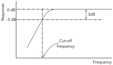
The shape of the curve is of importance. One of the most important features is the cut-off frequency. This is normally taken as the point where the response has fallen by 3dB, i.e. the voltage has fallen to 1/√2 or 70.7% of the in-band value.
Another important feature is the final slope of the roll off. This is generally governed by the number of 'poles' in the filter. Normally there is one pole for each capacitor or inductor in a filter.
When plotted on a logarithmic scale the ultimate roll-off becomes a straight line, with the response falling at the ultimate roll off rate. This is 6dB per pole within the filter.
The advantage of using an op amp circuit for the high pas filter, is that a multiple pole circuit can be made using just capacitors and resistors, rather than inductors that might otherwise be needed.
One transistor active high pass filter circuit
The transistor high pass filter circuit given below provides a two pole filter with unity gain. This means that the ultimate roll-off rate will be 12 dB per decade.
Using just a single transistor, this filter is convenient to place in a larger circuit because it contains few components and does not occupy too much space.
Being essential a form of emitter follower, this electronic circuit design provides only unity voltage gain for the in-band frequencies.
The active high pass transistor circuit design is quite straightforward, using just a total of four resistors, two capacitors and the single transistor. The operating conditions for the transistor are set up in the normal way. R2 and R3 are used to set up the bias point for the base of the transistor. Often this is set to give the base voltage at half the rail voltage so that the maximum voltage excursions can be made without running into the rail voltage.

The values of these resistors must also be set so that the overall value of the resistors in parallel does not affect the operation of the filter as we see below, whilst also being able to supply sufficient current for the base of the transistor.
The emitter resistor Re is the emitter resistor is calculated to give the required current through the transistor knowing the voltage on it as it will be 0.6 volts below the voltage that is on the base, for a silicon transistor. For a germanium transistor it is just 0.2 to 0.3 volts below the base voltage. Knowing the voltage on the emitter, it is then just a simple a simple Ohm's Law calculation to determine the value of the emitter resistor.
The filter components are included in negative feedback from the output of the circuit to the input. The components that form the active filter network consist of C1, C2, R1 and the combination of R2 and R3 in parallel, assuming that he input resistance to the emitter follower circuit are very high and can be ignored.
The capacitors should be reasonably close tolerance types - ceramic, metal film, etc are ideal. Aluminium electrolytic capacitors should not be used as these often have a tolerance of -20% and +50% and this might lead to some unwanted performance characteristics.
The equations for determining the component values provide a Butterworth response. This filter response provides maximum flatness within the passband at the expense of achieving the ultimate roll off as quickly as possible. This has been chosen because this form of filter suits most applications and the mathematics works out easily. Although this may not be the form of filter needed for all electronic circuit designs, it is more than suitable for the majority.
The equations for calculating the values in the one transistor high pass filter are given below:
So that the loading on the filter components is minimal and the calculations are not offset by the loading effect of the transistor itself:
Where:
Β = the forward current gain of the transistor
f0 = the cut-off frequency of the high pass filter
π = the greek letter pi and is equal to 3.14159
When designing the circuit, a little iteration may be required to optimise the value so that available components can be used and impedance values, etc can fall within acceptable limts.
The simple two pole active high pass filter circuit enables a simple circuit to be incorporated into areas where it may not be convenient to use another approach. The simple calculations and the few components used make it ideal to use.
This one transistor high pass filter circuit can be used when there is a need for a circuit to eliminate low frequency hum, but retain the high frequency audio, etc . .
More Circuits & Circuit Design:
Op Amp basics
Op Amp circuits
Power supply circuits
Transistor design
Transistor Darlington
Transistor circuits
FET circuits
Circuit symbols
Return to Circuit Design menu . . .


