
Transistor Schmitt Trigger Circuit
Understand the Schmitt trigger circuit which is often used to prevent repeated triggering, & it is easily implemented as a transistor circuit design.
Transistor Circuit Collection Include:
Transistor circuit collection
Common emitter
Emitter follower
Common base
Darlington pair
Sziklai pair
Current mirror
Long tailed pair
Constant current source
Capacitance multiplier
Two transistor amplifier
High pass filter
Switch circuits
Pulse generator
Schmitt trigger
One transistor relaxation oscillator
Transistor crystal-oscillator
See also:
Transistor circuit design
The Schmitt trigger is a very useful circuit that has hysteresis i.e. the switch points from low to high and high to low occur at different voltages.
The hysteresis of the Schmitt trigger is particularly useful because it enables circuits that might use a varying signal to switch in a more defined manner. It is less likely to switch up and down as the trigger voltage approaches.
As a result, Schmitt trigger circuits are widely used with sensors and a variety of areas where a trigger is needed when a specific level needs to be detected on a changing or varying voltage level.
Who was Schmitt
The Schmitt trigger is used in many circuits, made from both discrete components, or as part of an integrated circuit. The concept of the trigger is widely used.
The concept of the Schmitt trigger was conceived around 1934 by an American graduate student named Otto Schmitt when he described the concept in his doctoral thesis in 1934.
As a result he is credited with either inventing, or co-inventing the idea which now bears his name.
Basis of the Schmitt trigger circuit
The Schmitt trigger is important because this type of electronic circuit design changes its output value at a certain value, but retains this until there is a sufficient reversal of the change to return the output to its original value.
The circuit is said to have a hysteresis. As an example, when the input is below a lower threshold the output is low, then as the input moves higher, the output transitions to a higher value, but it then needs to move lower than the first transition point for the output to return to its original low value.

Looking at the diagram, it can be seen that the output switches on the higher voltage, but returns to its lower value when there is a lower value present on the input.
The various circuit conditions can be changed, but the essential element is that for the output a different value is required for each direction of change.
This is particularly useful when there is a slow edge or an analogue signal that needs to be converted to a digital one. If a straight comparator was used, then any noise on the signal could result in multiple transitions of the output as the noise meant that the switching threshold was crossed multiple times.
However using a Schmitt trigger, the input needs to switch over a wider range to cause the output to change. If the hysteresis level is designed such that it exceeds the noise level, then the output will not undergo multiple transitions where one was needed. If it did then this could cause havoc with any logic or other signals that might depend upon the output of the comparator or Schmitt trigger.
To explain the concept of hysteresis with an example, take the situation where there is a reference voltage of, 5 volts, for example. As the voltage rises, dependent upon the circuit is for example 5.5 volts. Then to switch in the other direction, the input voltage must fall to, for example 4.5 volts.
In this way, there is a 1 volt difference between the switching in either direction, and this provides some significant noise immunity.
Schmitt trigger circuit symbol
On some occasions a Schmitt trigger may be shown in a block diagram with a specific circuit symbol as shown below.
It can be seen that the circuit symbol is made up from the amplifier symbol and within it there is the hysteresis shape. This combines the two elements of the Schmitt trigger.

Although we are focussing on a transistor implementation of the Schmitt trigger, it is useful to see the block diagram symbol.
Circuit design alternatives
There are many ways of realising a Schmitt trigger circuit design. Some may appear to be easier than others, but dependent upon the situation and the circuit design requirements, one option may be better than another.
Logic chip incorporating Schmitt trigger: There are very many logic chips that are labelled as Schmitt triggers. These are ideal for use with logic circuit applications, but it is not possible to select the trigger voltages. They have been designed with the specific needs of logic circuits in mind and work very well for these specific situations, but they are not customisable.
Comparator IC: Using a comparator IC is possibly the most usual path to follow to design a trigger circuit to meet specific requirements. Comparator ICs are cheap and easy to buy, so this can be a very good option for many electronic circuit designs. As the comparators are very fast, this can be ideal for many designs.
Discrete components: Using discrete transistors (or FETs) is another good option when it is necessary to be able to customise the circuit. The transistors may well be available, and the circuit can be put together using a few electronic components.
Using discrete transistors may be the best option for some situations, although it is always best to consider all the options before making a decision.
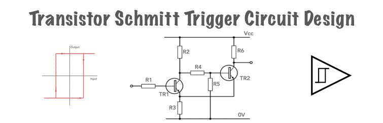
Transistor Schmitt trigger circuit design
The circuit of the transistor based Schmitt trigger is based around a two transistor configuration and it incorporates the concept of the two switching transition states by applying positive feedback within the circuit.
The actual hysteresis within the circuit works because there is a voltage divider incorporated within the circuit and this has a switchable upper leg with the transistor collector resistors R3 and R6 within the circuit, and the lower leg is provided by R3.

The transistor TR1 acts as a comparator having differential inputs with the base of TR1 providing the inverting input, and the emitter as the non-inverting input.
The incoming waveform is applied to the base of TR1 via a resistor to ensure the base current is suitably limited by R1. The output voltage of the voltage divider is applied to the non-inverting input at the emitter of TR1. The voltage at the emitter determines the threshold of the comparator as the base must be more than 0.6 or 0.7 volts above the base to switch.
The output from this comparator is then applied to a second transistor, TR2 through the resistor voltage divider network consisting of R4 and R5.
It can be seen that the overall circuit consisting of two transistors switches over two aspects. It switches the upper legs of the voltage divider and also changes the threshold of the circuit.
It is also possible to consider this Schmitt trigger circuit as a differential amplifier with series positive feedback. However there is also a small amount of negative feedback resulting from the resistor, R3. In order for the circuit to operate satisfactorily R2 ≥ R6.
In this way less current flows through R3 from TR1. This results in voltage changes across R3 being much less when TR1 switches than when TR2 switches.
It is possible to determine the threshold voltages for the high and low switching.
High switching threshold
Low switching threshold
Where:
VH = high threshold voltage
VL = low threshold voltage
Vcc = supply voltage
Note: the calculations above have some approximations, and ignore the value of VBE for the transistors.
Schmitt trigger applications
Schmitt triggers are used for a wide variety of different purposes within various electronic circuits and systems.
The way in which they trigger on different voltages for each direction of output switching means they are ideal where any noise could cause a problem.
Some of their applications include the following:
Level detection: One of the most obvious uses for the Schmitt trigger is for level detection. When used for this, it is necessary that the hysteresis voltage is taken into account during the electronic circuit design so that the circuit switches on the required voltages both ways.
Digital to analogue conversion: The Schmitt trigger is effectively a one bit analogue to digital converter. When the signal reaches a given level it switches from one state to the other. This can then be used to drive other digital circuits.
Line reception: One of the issues with any wired data line is that it will pick up noise - even if it is well screened. Spurious switching caused by noise will play havoc wit the system. The Schmitt trigger is an ideal circuit to use to ensure that the logic output level of the line receiver is only changed as the data changed and not as a result of spurious noise that may have been picked up. Using a Schmitt trigger broadly enables the peak to peak noise to reach the level of the hysteresis before spurious triggering may occur.
There are obviously very many other situations where Schmitt triggers can be used to enable circuits to work well, but these are some that are particularly useful and widespread.
Circuit design hints and tips
The transistor version of the Schmitt trigger is relatively easy to design, but as with any electronic circuit design, there are a few pointers to watch out for - fortunately not too many though.
Setting the trigger voltages: Careful determination of the best trigger voltages is one of the keys to successful design of these electronic circuits.
Normally the transistor Schmitt trigger is easy to design and as it uses two main states, there are normally few issues with the designs and circuit implementations.
Although there are comparators and even dedicated Schmitt trigger ICs, there are many instances when a transistor version using discrete components may be needed. Accordingly having an understanding of how the circuit works and the circuit diagram can be very helpful.
More Circuits & Circuit Design:
Op Amp basics
Op Amp circuits
Power supply circuits
Transistor design
Transistor Darlington
Transistor circuits
FET circuits
Circuit symbols
Return to Circuit Design menu . . .

