
What is an Oscilloscope: basics & fundamentals
The oscilloscope is one of the most useful test instruments used for electronic circuit design, electronics manufacture, test, service, and repair.
Oscilloscope Tutorial Includes:
Oscilloscope basics
Oscilloscope types
Specifications
How to use an oscilloscope
Scope triggering
Oscilloscope probes
Oscilloscope probe specifications
Scope types includes:
Analogue scope
Analogue storage scope
Digital phosphor scope
Digital scope
USB / PC scope
Mixed Signal Oscilloscope MSO
Oscilloscopes, or scopes are an important tool in the armoury of the electronics engineer or tester. An oscilloscope is an item of electronics test equipment that enables waveforms to be seen and in this way makes it very much easier to see any problems occurring in an electronics circuit.
In view of the advantages which they posses, oscilloscopes are an essential piece of electronics test equipment for any electronics laboratory or area testing electronics hardware whether within RF design, general electronics circuit design, electronics manufacturing, service, repair or anywhere that electronic circuits and the waveforms on them need to be investigated.
The name oscilloscope, comes from the fact that it enables oscillations to be viewed. Sometimes the name cathode-ray oscilloscope, or CRO was used. The reason for this was that cathode ray tubes (CRT) were used to display the waveforms. Nowadays these test instruments just tend to be referred to as oscilloscopes, or just scopes.
Video: What is an Oscilloscope: introduction
Today, LCDs, or plasma displays are used as they are smaller, and more convenient to use, especially as the do not require the very high voltages of the old CRTs.
Function of an oscilloscope
The function of an oscilloscope is to be able to display waveforms on some form of display. In the normal mode of operation time is displayed along the X-axis (horizontal axis) and amplitude is displayed along the Y axis (vertical axis). In this way it is possible to see an electronic waveform on an oscilloscope as it may be envisaged. The waveform could be likened to that of the ripples on travelling along the surface of a pond when a stone is dropped into it.
By seeing a waveform in this manner it is possible to see analyse the operation of the circuit and discover why any problems may exist.

Key oscilloscope topics
When looking at oscilloscope there are several key topics and areas of interest:
Types of oscilloscope: There are several different types of oscilloscope from analogue to digital and more. The first types of oscilloscope were analogue, but with the advances in digital technology, virtually all new test instruments these days are processor controlled and use digital signal processing to provide excellent displays of the waveforms.
Not only are there oscilloscopes contained in standard bench style boxes, but some scopes are designed to link to computers, using their display and processing to assist. Often they are USB oscilloscopes, connected via USB links but other types are also available linked via other bus systems or for use within rack systems like PXI and the older VXI systems..
Read more about . . . . Oscilloscope types.
Scope specifications: The specifications for oscilloscopes can sometimes be confusing. A basic understanding of the terms and what they mean is very useful. Understanding the basic oscilloscope specifications can provide an understanding of the limitations of any given test instrument and also help in the selection when one needs to be hired, bought or even booked out of a common store.
The scope specifications are slightly different between the analogue and digital scopes. Although basic concepts like accuracy, time base range, upper frequencies and the like are essentially the same, digital scopes also have specifications to items like the number of DAC bits, memory depth and the like that are specific to digital oscilloscopes.
Read more about . . . . Oscilloscope specifications.
How to use an oscilloscope: Although oscilloscopes are easy to use these days, it helps to have an understanding of how these items of electronics test equipment work and what controls there are and how they operate. There are even soft keys on the screen, so there is a lot that can be done.
Normally the most widely used controls are common across all scopes from whatever manufacturer, so moving from one scope to another is often relatively easy.
Read more about . . . . How to Use an Oscilloscope.
Oscilloscope triggering: The trigger function is one of the most important functions on an oscilloscope. The scope trigger enables the timebase to "start" at the same point on each cycle of the waveform and this enables to be displayed so it appears still on the screen.
The oscilloscope trigger function has developed considerably since most scopes moved to use digital technology. The digital signal processing available enables the trigger to provide more flexibility and greater functionality so that signals can be investigated more closely to discover problems and issues.
Read more about . . . . Oscilloscope Triggering.
Oscilloscope probes: Any oscilloscope will need probes to attach to the unit under test. The performance and use of these scope probes enables the best to be made of the actual test instrument, so knowing which probes to select, how to set them up, and the limitations are essential for a true understanding of the measurements made.
Read more about . . . . Scope Probes.
Development of the oscilloscope
The oscilloscope was developed over many years. It took a large number of new discoveries and inventions for it to arrive at the level of sophistication we see today.
The history of the oscilloscope dates back over 100 years, each step the result of innovation, inspiration and hard work.
| Key stages in the Development & History of the Oscilloscope | |
|---|---|
| Date | Discovery / Development |
| 1897 | Karl Ferdinand Braun invented the first Cathode Ray Tube, CRT. It could display crude figures on the screen controlled by voltages on the plates of the tube. |
| 1899 | Jonathan Zenneck improved the basic cathode ray tube by incorporating beam-forming plates and using a magnetic field for sweeping the trace. |
| 1931 | V. K. Zworykin improved the cathode ray tube when he detailed a permanently sealed, high-vacuum cathode ray tube with a thermionic emitter. This enabled General Radio to manufacture an oscilloscope that was usable outside a laboratory setting. |
| Late 1930s | The British company A C Cossor invented a dual beam oscilloscope which was widely used during WW2 for servicing electronics equipment and in particular the radar systems. |
| 1946 | The triggered sweep oscilloscope was invented by Howard Vollum and Jack Murdock. This made the oscilloscope much easier to use as waveforms were able to be displayed in a steady manner. |
| 1946 | Tektronix was founded by Howard Vollum and Jack Murdock. |
| 1963 | Tektronix introduced the Direct View Bistable Storage Tube (DVBST). This allowed single pulse waveforms to be displayed rather than just repeating waveforms. |
| The Digital Storage Oscilloscope, DSO was invented by Walter LeCroy after producing high-speed digitizers for the research centre CERN in Switzerland. Walter LeCroy later founded the LeCroy Corporation. | |
Oscilloscope exterior
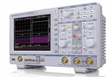
An oscilloscope will normally have a large array of items on the exterior of the case.
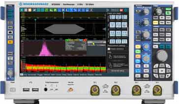
The front panel of the test equipment will typically have a number of items on it:
- Display The first things that is noticed on an oscilloscope is the large display that is used for displaying the waveform. This typically may take around a quarter of the space on the front panel or even a little more. It is often good to have a reasonably large display then it is easier to see the various elements of the waveform.
- Connectors There is a variety of different connectors on the front panel. Typically there is an input for each of the channels to be displayed - often an oscilloscope will have more than one channel. Many oscilloscopes are dual channel and can therefore display two signals at the same time, allowing waveforms to be compared. Other inputs may include a trigger input that will enable the trace on the oscilloscope to be triggered according to this signal.
- Controls There is a variety of controls on the oscilloscope:
- Vertical gain / signal input sensitivity: This is generally calibrated in V/cm, i.e. each vertical division on the scale represents a given number of volts.
- Timebase: This alters the speed at which the trace crosses the screen horizontally on the oscilloscope. It is calibrated in terms of time / division, e.g. 1ms / cm, assuming the divisions are at one centimetre intervals.
- Trigger: The controls that are associated with the trigger enable the timebase of the oscilloscope to be triggered in various ways. This enables a still or stable picture to be obtained on the screen of the oscilloscope.
In order to be able to operate the oscilloscope correctly it is necessary to connect the right signals into the inputs, and also to use the controls correctly.
Oscilloscopes are one of the more widely used items of electronics test equipment. They provide a high level of insight into the operation of a circuit and they are key to finding many issues and resolving them, whether in general electronic circuit design, RF design, electronics manufacturing test, service, repair and even field service.
More Test Topics:
Data network analyzer
Digital Multimeter
Frequency counter
Oscilloscope
Signal generators
Spectrum analyzer
LCR meter
Dip meter, GDO
Logic analyzer
RF power meter
RF signal generator
Logic probe
PAT testing & testers
Time domain reflectometer
Vector network analyzer
PXI
GPIB
Boundary scan / JTAG
Data acquisition
Return to Test menu . . .

