
Oscilloscope Trigger: Triggering a Scope
The trigger function is one of the most useful functions on the oscilloscope - knowing how to use the scope trigger is key to being able to use it effectively.
Oscilloscope Tutorial Includes:
Oscilloscope basics
Oscilloscope types
Specifications
How to use an oscilloscope
Scope triggering
Oscilloscope probes
Oscilloscope probe specifications
Scope types includes:
Analogue scope
Analogue storage scope
Digital phosphor scope
Digital scope
USB / PC scope
Mixed Signal Oscilloscope MSO
The oscilloscope trigger function enables repetitive waveforms to be displayed on the screen in steady fashion. The trigger enables the timebase to start its scan at the same point on each repetition of the waveform.
In this way the oscilloscope trigger enables the waveforms to be viewed in a meaningful manner, otherwise the timebase would start at a random point on the waveform each time the waveform is repeated and the image of the waveform would not be meaningful.
Video: oscilloscope triggering
Oscilloscope trigger concept
The basic concept behind the oscilloscope trigger function is that some of the incoming waveform is fed into comparator circuit.
When the voltage of the waveform reaches a required level, then a comparator switches and send a start signal to the timebase. This enables the timebase to exactly synchronise with the displayed waveform so that it remains stable on the screen.

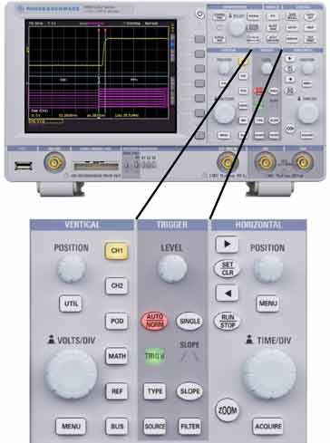
Oscilloscope trigger level and slope
In order to be able to capture the required view on the scope, the trigger can be adjusted in two main ways: both the level and the direction of the slope can be selected on both analogue and digital oscilloscopes.
The trigger voltage level control sets the voltage at which the trigger fires. Changing this voltage changes the point on the waveform where the timebase starts.

It can be seen that by altering the trigger voltage, the position on the waveform is varied.
The trigger slope, as the name indicates, determines whether the time-base sweep is triggered on a positive or negative going edge or slope.

Oscilloscope trigger sources
The waveform on which the oscilloscope can trigger can be sourced in a variety of ways. Sometimes having an external source for triggering can make the waveform more stable and enable the waveform to be seen in a more stable form.
- Signal channel: The most common source of the waveform used for providing the trigger is the signal channel itself. On multiple channel scopes the trigger defaults to the A channel, but normally it is also possible to trigger on other channels as well. Triggering may be marked A / B channel, or equivalent
- External source: On most scopes there is the possibility of selecting an external trigger source. This can be very useful when a system is synchronised to an external signal. It is normally possible to have the same control of trigger voltage and slope for these external signals.
- Video: The video trigger was widely used for analogue video and television applications. The trigger circuit extracted the synchronisation, sync pulses that were embedded in the analogue video signal and used this.
- Line: Using the line trigger facility, the scope would trigger on the power input, or line voltage waveform. This form of triggering was useful for detecting line associated issues.
Trigger hold-off
One capability that is particularly useful when triggering more complicated waveforms is known as the trigger hold-off control.
It is probably easiest to explain the operation of the trigger hold-off in terms of analogue scopes.
Once the scope sweep has completed, the beam is blanked and the scope returns the sweep voltage back to the starting point. By blanking the beam or trace, the flyback is not seen on screen.
During the sweep and flyback or retrace the trigger circuit will ignore any further trigger pulses that may arrive and it is 'held-off' until the sweep and the retrace have been completed.
Once the trace is back at the start point it is ready to trigger again, and the first point on a waveform that appears will cause it to start again.

The Trigger Hold-off control provides the ability for the user of the scope to add an additional, delay to the re-arming of the trigger circuit, beyond the end of the sweep/retrace period. This gives control over how rapidly the oscilloscope can be triggered. When some waveforms have several points at which they can trigger the scope, it can help add clarity to the displayed image on the scope.
For the waveform above, the scope would trigger on the first pulse after the end of the displayed area, and in this example, this is not what is needed and it would lead to an unsteady display.
Although this was explained in terms of analogue scopes, the same process is available in digital ones, although the working under the front panel will be somewhat different.
Oscilloscope auto-trigger
The trigger facility is fine when a signal is present and the scope is triggering. However when no signal is present, it is useful to be able to see where the trace is, for example, to set the trace to a particular place on the screen before applying the signal and making a measurement.
To overcome the lack on trace under no or small signal conditions an auto-trigger capability is added.
The scope auto-trigger will start the sweep if no signal is present. A timer within the scope detects that the scope has not been triggered for a while and sets the sweep in motion. The delay can often be set.
For most general use of the oscilloscope, it can be left in auto-trigger mode, and only set to “normal” for more exacting measurements and waveforms.
Advanced oscilloscope triggering options
With the advent of digital scopes, there are many possibilities for advanced triggering options. These can all be used to help locate and display waveforms that may require more complex triggering options. However with the software in digital scopes this can now be achieved whereas it would not have been possible with analogue scopes.
- A & B triggering: Although many scopes offer triggering from the A and B channels, some digital scopes offer more complex triggering options for A and B channels. For example they may offer logic qualification to control when to look for various events. Others may have a form of delayed triggering a set time after a previous trigger event.
- Serial pattern triggering: This form of trigger looks at a serial data stream and triggers after a given serial pattern is seen. This can be particaulrly useful when testing or debugging digital or microprocessor based circuits.
- Search and mark : This form of trigger scans for a multiple event types before triggering. Individual marks can be added to portions of the sweep to highlight areas.
- Trigger correction: It is sometimes necessary to be correct for trigger delays in very fast systems. As the trigger and signal paths have different times delays there is an inherent time difference between the trigger position and the data that is acquired. This can result in jitter on the display or in skew. To overcome this, a trigger correction system is employed that compensates for the delay differences between the trigger and data acquisition paths. When used in this mode, the trigger point can be used as a reference point for the measurement.
The oscilloscope triggering system forms one of the key elements of the overall test instrument. With the complexity of equipment increasing, this also results in a rising level of waveform complexity, for which the more sophisticated trigger systems are required. As a result most new oscilloscopes are offering more comprehensive triggering options.
More Test Topics:
Data network analyzer
Digital Multimeter
Frequency counter
Oscilloscope
Signal generators
Spectrum analyzer
LCR meter
Dip meter, GDO
Logic analyzer
RF power meter
RF signal generator
Logic probe
PAT testing & testers
Time domain reflectometer
Vector network analyzer
PXI
GPIB
Boundary scan / JTAG
Data acquisition
Return to Test menu . . .

