
Function Generators Explained
Understand exactly what function generators are, how they are used & how they generate waveforms with common shapes: sine, square, pulse, triangular etc . . . .
Function Generators includes:
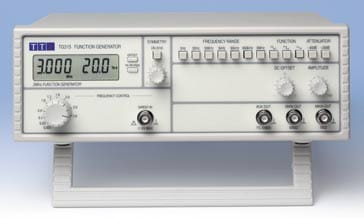
Function generator
Function generator specs
Signal generator types: Signal Generator Basics RF signal generator basics Arbitrary waveform generator Pulse generator
A function generator is a specific form of signal generator that is able to generate waveforms with common shapes.
Unlike RF generators and some others that only create sine waves, the function generator is able to create repetitive waveforms with a number of common shapes.
In particular it can be made to become a sine wave generator, square wave generator, and triangular wave generator.
Also a function generator may be able to vary the characteristics of the waveforms, changing the length of the pulse, i.e. the mark space ratio, or the ramps of the different edges of triangular or sawtooth waveforms.
The function generator is only be able to create the waveforms that are built in to the function generator. It cannot be programmed to create additional waveforms - an arbitrary waveform generator, AWG is required for this.
Apart from just generating the waveforms themselves, this type of test instrument has the capability to add a DC offset to the signal. This can be very useful in a number of testing applications.
Typically function generators are only able to operate at relatively low frequencies, some only operating to frequencies of around 100kHz, although more costly test instruments can operate at higher frequencies, up to 20 or 30MHz.
It is also interesting to note that many oscilloscopes now include a function generator - this can be included quite easily in many designs, and therefore manufacturers believe this will give their product additional functionality and appeal.
Function generator capabilities
The name of the function generator arises from the fact that it is able to generate a number of different functions or waveforms.
Function generators are capable of producing a variety of commonly used repetitive waveforms. The waveforms generated will generally be a sine wave, square wave, sawtooth, pulsed, etc.
With a function generator, there is no capability to have user generated waveforms, as it then would become an arbitrary waveform generator.
Square wave: Another very widely used waveform is the square wave. It consists of a signal moving directly between high and low levels. Used as a square wave generator, this test instrument provides a very useful source of a basic digital waveform.

Square waves may primarily be used for logic or digital circuit testing. The square wave could be used as a clock for a circuit, or there are many other instances were a square wave can be useful.
When using a function generator for a digital circuit, it is necessary to make sure the rise and fall times of the edges are fast enough. Typically the output from a function generator will be quite fast, but as some logic circuits require very fast edges, this is worth noting. Also any test leads carrying the signals could slow the edges.
One way to overcome this type of issue is to make sure that there is a buffer at the input of the board to ensure that all edges are fast enough.
- Pulse: A pulse waveform is another type that can be produced by a function generator. It is effectively the same as a square wave, but with the mark space ratio very different to 1:1. This form of waveform is again often used within digital applications.

For function generators that incorporate a pulse waveform capability, there may be an adjustment to change the mark space ratio. Typically a pulse signal will be used to provide a rising or falling edge as a clock signal, so the actual mark space ratio is not always important.
As with the square wave, the speed of the rising and falling edges can be important whan driving a logic circuit.
Triangular wave: This form of signal produced by the function generator linearly moves between a high and low point. This form of waveform is often generated using an operational amplifier acting as an integrator. The triangular waveform generator typically also has a square wave output as well, and it is used as the basis for generating all the waveforms in a function generator test instrument.

The triangular waveform is often used in testing amplifiers - it is far easier to see distortion and clipping on a triangular waveform than it is on a sine waveform.
- Sawtooth wave: Again, this is a triangular waveform, but with the rise edge of the waveform faster or slower than the fall, making a form of shape similar to a sawtooth.
The waveform is generated by the same circuit as the triangular waveform, but with the different rise and fall times created by changing the charge rate for the rise and fall elements of the integrator.

Often the sorter element of the sawtooth is made to be as fast as possible. These waveforms were widely used in cathode ray displays where the slower increasing voltage was used to enable the scane to proceed across the screen, but a very fast flyback was required so that the next scan could start.

A sine wave is always useful as it provides a single frequency signal - other waveform formats have harmonicas. A sine wave can be used for many electronic circuits, especially analogue ones where the only the basic single frequency is needed.
These are the basic waveforms that are produced within a function generator test instrument. These waveforms satisfy most of the needs for testing a number of items. Where specialised waveforms are required, then an arbitrary waveform generator is required.
To find out more about these waveforms check out the video below which covers the main waveforms generated by function generators.
Video: Electronic Waveforms: sine, square, rectangular, triangular, sawtooth
Function generator controls
In addition to a selection of the basic waveforms that are available, other controls on the function generator may include:
- Frequency: As would be expected, this control alters the basic frequency at which the waveform repeats. It is independent of the waveform type.
- Waveform type : This enables the different basic waveform types to be selected:
- Sine wave
- Square wave
- Triangular wave
- DC offset: This alters the average voltage of a signal relative to 0V or ground.
- Duty cycle: This control on the function generator changes the ratio of high voltage to low voltage time in a square wave signal, i.e. changing the waveform from a square wave with a 1:1 duty cycle to a pulse waveform, or a triangular waveform with equal rise and fall times to a sawtooth.
Function generator usage
Function generators are normally used within electronics development, manufacturing test and service departments. They provide a flexible form of waveform generation that can be used in many tests.
These test instruments are very flexible and not thought of as specialist instruments. Although they can often generate signals into the low end of the RF spectrum, normally a specific RF generator would be used, unless none were available.
Also they are generally not used for performance audio testing as the levels of distortion on the sine aves that would normally be used would have higher levels of distortion than these tests sometimes require. A typical figure for the sine wave distortion might be about 1%.
If very high frequency stability is required, then some of these test instruments allow for the output signal to be phase locked to another source.
Types of function generator
There are a number of ways of designing function generator circuits. However there are two main approaches that may be used:
- Analogue function generator: This type of function generator was the first type to be developed. First models appeared in the early 1950s when digital technology was not widely used.
Despite the fact that they use analogue technology, these analogue function generators offer a number of advantages:
- Cost effective: Analogue function generators are very cost effective, being at the lower end of the function generator price range.
- Simple to use: Analogue function generators provide an effective test instrument that is able to meet most user needs, while remaining simple and easy to use.
- Maximum frequencies: The analogue function generators do not have the high frequency limitations on non-sinusoidal waveforms such as triangles and ramps as do the digital function generators.
Digital function generator: As the name indicates, digital function generators utilise digital technology to generate the waveforms. There are a number of ways in which this can be done, but the most versatile and most widely used technique for digital function generators is to use direct digital synthesis, DDS.
DDS uses a phase accumulator, a look-up table containing a digital representation of the waveform, and a DAC. The phase accumulator moves another position each time it receives a clock pulse. The next position in the look-up table is then accessed giving the digital value for the waveform at that point. This digital value is then converted into an analogue value using a digital to analogue converter, DAC.
Digital function generators are able to offer high levels of accuracy and stability because the clock for the system is crystal controlled. Also digital function generators provide a high spectral purity and low phase noise. A DDS based digital function generator can also can be swept over a much wider frequency range than an analogue function generator. It can also perform a number of other functions such as phase continuous frequency hopping because of the action of the direct digital synthesizer.
The disadvantage of the digital function generators is that they are more comprehensive than their analogue cousins, they require a high performance DAC and other digital circuitry and this means they are more costly and also more complicated to sue as a result of their additional functionality
- Sweep function generator: A sweep function generator is simply one that can sweep its frequency. Typically the more versatile sweep function generators utilise digital technology, but it is also possible to use analogue versions as well.
Sweep function generators may be able to sweep over ranges of up to 100:1 or more, although this is very dependent upon the actual generator type in question. Speed of the sweep may also be important. Another feature that may be of importance is whether the sweep is linear or logarithmic. Some function generators may have a switch for this.
Most current function generators adopt a digital approach to the waveform generation. Some older function generators may use analogue techniques, but it is unlikely that any new ones will.
Function generator formats
There are several forms that the function generator can take. With modern digital technology there are many formats for this type of test equipment.
The format for the function generator will depend on factors including the approach that will be adopted for testing, and the environment in which it will be used - rack testing, bench-top testing, or wil an accompanying computer be available for control.
- Bench top test instrument: The most widely used form of function generator in the test laboratory is the test instrument contained within a box that sits on the laboratory bench. This test instrument contains the power supply, controls, display and of course the output connector.
- Rack based test instrument: Another format that this type of test equipment can take is a module within a rack system like PXI. Based on PCI, the PXI rack system has been developed specifically for test applications and includes a slot for either a controller or link to a computer. Test instrument cards slot into the chassis, enabling a test system to be created to meet the needs of the particular test application required. The test instrument cards can include any type of test instrument including volt meters, oscilloscopes, and of course a function generator
- USB function generator: A number of small function generators are available as USB based test instruments. They contain the core oft he function generator within the module that connects to a computer via a USB connection. This approach means that the power and control interfaces can use the PC rather than having the expense and space required to provide these within a larger box for the test instrument.
- Computer based function generator: A different approach is to use software based within a computer to provide the required waveforms and then use a digital card of the computer's audio output for the signal. Whilst very cheap, this may not have the output capability and accuracy of other types of test instrument. Also if the output is damaged as a result of the testing and a possible misconnection, etc it can result in costly repairs.
- Within oscilloscopes: Often oscilloscopes contain a simple function generator. As these instruments are relatively easy to construct, they can be incorporated into a scope for little additional cost and enable them to have an onboard signal source which can be very useful on a number of occasions.
It is necessary to assess exactly what is needed so that the most cost effective solution is found to a requirement for a function generator.
Function generator circuit block diagram
Function generators may be designed using one of two basic technologies or design approaches. They may use analogue techniques,or they may use a digital approach.
Of the two the digital approach is more widely used these days, but the analogiue versions were the first to be designed as the ywere used before digital technology had advanced to mayke this approach viable.
• Analogue function generator block diagram
There may be a number of ways in which an analogue function generator may be designed, but the block diagram of the one shown below adopts the sort of approach most widely used.
An osillator based around an integrator and a Schmitt trigger was used to generate the triangular and square waves, and then the triangualr waveofmr was passed through a shaping circuit to provide the sine wave.

Looking at the circuit block diagram in more detail, the heart of the circuit is formed by the combination of the integrator and the Schmitt trigger.
The integrator takes the voltage at the input and the output voltage rises linearly until a point is reached where the Schmitt trigger triggers and the output changes. This is used to drive the input to the integrator and its is in such a sense that the integrator voltage now falls.
The Schmitt trigger can often be used directly for this, or a current source may be used - using a dedicated current source, typically one for each sense is much better because it enables the drive to the integrator to be more what is required.
The output from the Schmitt trigger is a square waveform, and this can be take directly to switch to select the type of waveform and then to a buffer amplifier. This prevents any loading on the output of the Schmitt trigger hat might alter the integrity of the square wave.
The output from the integrator is a triangular wave and this can be taken tot he waveform type selector switch and again this is buffered for the same reasons.
Finally the triangular waveform output of the integrator is taken via a buffer amplifier to a waveform shaper to convert the triangular waveform into a sine wave. This network typically consists of a resistor diode network which removes the sharp peak and generally shapes the waveform to provide a sine wave.
It should be noted that the output from the Schmitt trigger must enable the integrator to rise and fall at exactly the same rate if a true triangular wave, a square wave with a 1:1 mark space ratio and a good sine wave are to be produced.
• Digital function generator block diagram
More commonly these days, a digital approach is adopted to generate the function outputs. Using a digital approach these days enables much greater levels of performance and flexibility.
Also with the costs of the digital components needed now much lower and the top frequencies much higher, this approach is normally the ideal option.
Essentially a form of direct digital frequency synthesizer is used. The circuitry can be contained in just a few chips along with a few other electronic components, and the performance is normally very high.

The phase increment signal determines the frequency of the output signal and the clock can be a simple crystal oscillator which wil enable a very frequency stable output signal to be generated.
The output filtering is key to many of the specifications, and this removes many of the unwanted products.
The different waveforms required can be stored in the waveform map ROM, and this enables a wide variety of waveforms to be stored and used.
Function generator specifications
The specifications of function generators are obviously important when testing circuits. The performance must exceed that of the requirements for the circuit under test.
Accordingly the various factors that need to be assessed must be carefully investigated to ensure they meet the requirements for the testing so that erroneous testing does not occur.
Factors including the frequency range, output voltage range, square and pulse waveform rise and fall times, and several other aspects are all important. It is also worth checking that the frequency stability is sufficient because many function generators can use low stability oscillators within their circuits.
Function generators are normally very easy to operate. With modern processing technology often included this gives the possibility of many additional features including ease of operation, and remote control via one or more of the many standards available.
A good variety of function generators are available for a number of different manufacturers and also via a number of different distributors. Costs are usually quite reasonable as they are normally quite straightforward and do not require very high frequency components. These test instruments can be either analogue or digital. Analogue ones tend to use operational amplifiers as the basis of the design, but digital ones can use some form of direct digital synthesis.
More Test Topics:
Data network analyzer
Digital Multimeter
Frequency counter
Oscilloscope
Signal generators
Spectrum analyzer
LCR meter
Dip meter, GDO
Logic analyzer
RF power meter
RF signal generator
Logic probe
PAT testing & testers
Time domain reflectometer
Vector network analyzer
PXI
GPIB
Boundary scan / JTAG
Data acquisition
Return to Test menu . . .

