Options for Breadboards for Electronic Circuit Prototypes & Hook-Ups
Understand the different ways and options for breadboarding or building electronic circuits: prototypes, breadboards, circuit boards, PCBs, stripboards, general hook-ups
Home » Construction & manufacture » this page
Building Electronic Circuits & Prototyping Includes:
Breadboard options for electronic circuits
There are many ways to build electronic circuits, but often when a breadboard is being hooked up, what is often needed is something that is quick and easy.
There are many good ways of breadboarding a circuit, so that a circuit idea can be tested or some function built to see how it works.
However it is worth having an idea of the various methods available, so that the best one can be chosen for the particular situation and circuit design being built.
Solderless strip board
One of the ways in which basic circuits can be built up is using a solderless form of breadboard or strip board.
These breadboard systems come in a variety of forms, but one type that is often used for beginners or making temporary circuits has a plastic base, and a variety of holes into which component leads can be inserted.
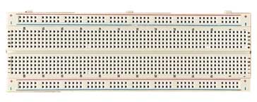
These breadboards enable the components to be inserted into the holes and connected under the surface so that they can provide an easy way of connecting components together.
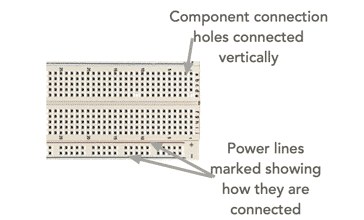
There are connection strips under the top surface of the breadboard system.
The top rows are typically connected lengthwise for the power rails. Often there are two at the top and two at the bottom and this enables two different power rails to be used, or they can be doubled up by connecting the top ones to the bottom ones.
The individual component rows are connected vertically and enable the individual components in the electronic circuit to be connected.
When using these breadboards, there are a few points which should be remembered:
Check the circuit thoroughly: Having put the electronic circuit together, check it very thoroughly afterwards. It is very easy to make mistakes as the format of the board will not make it easy to replicate the layout of the schematic.
Some boards have the power rails broken in the middle: It is worth checking the power rails - some have an intentional break in the middle and if this is so, the break can easily be linked with a short linking wire.
Check all the components are connected: It is quite easy, especially when using some of the cheaper boards for the components not to make good contact. Check each connection thoroughly to ensure it is making good contact.
Even though there are a few precautions to observe when using this form of breadboard, it is nevertheless a very useful format for many smaller circuits.
Video: Useful Electronics Breadboard System
There are plenty of versions of this type of breadboard available, often as part of an electronics kit containing additional components which allow the construction of a good number of electronic circuits and small projects.
Matrix board, pins and wiring
Another form of breadboard system which has been very good over the years is a matrix board.
As the name indicates the board consists of an insulating board that contains a matrix of holes - typically 0.1 inch (0.25cm) apart.
When using this board, there are special pins that can be inserted into the holes and the components can be connected to them above the board, and the underneath left for all the wiring.
Or the components can be inserted into the holes and the connections and wiring kept underneath.
Whatever way the wiring is done - my preferred method was to use the terminal pins - the use of this type of matrix board enables the components to be placed in a similar fashion to the circuit diagram, and this makes building, checking and faultfinding much easier.
Matrix board with wire strips
this form of matrix board, sometimes called a stripboard PCB has a matrix of copper strips on one side of the board enabling components to be mounted on one side of the board and their leads passed through the holes to the other side where the component leads can be soldered.
in this way it can appear a little like a printed circuit board and hence it is sometimes called stripboard PCB.
To enable sections of the strips to be isolated, a special tool or drill can be used to "drill" through the copper strip, but not the whole board. In this way different sections of the copper strips can be isolated enabling much more efficient use of the board.
Great care must be taken when drilling through the strips to ensure that the different sections are fully isolated. It is very easy to leave a thin whisker of copper and retain the connection between the two sections. Many people have been caught out by this because often these thin whiskers are easy to miss and they will totally wreck the function of the board.
Printed circuit board
In some circumstances a printed circuit board is appropriate to be used for prototype electronic circuits.
Although it can mean committing a lot of circuitry to a board, often in advance of it being tested, there can be advantages to this especially for large circuits using high speeds. Often large electronics companies will have designs on CAD systems and it is often possible to run many simulations before committing to the circuit board.
It was also possible to have home made circuit boards. The process was relatively simple, first marking out the position of the tracks on a copper clad board using a pen that has etch resistant ink, followed by etching the copper clad board in the etch fluid, and then thoroughly cleaning it before drilling the holes for the component leads.
Sadly the kits and items for doing this are not widely available these days because of health and safety concerns.
However professionally made PCBs can be made, but at a cost that is really only viable for commercial organisations.
There are many methods that can be used for breadboarding an electronic circuit design, but it is always wise to consider what method will be best for your particular situation. Some methods suit home construction much better, whereas others are more suited to commercial development. Some may be suited to a temporary "hook-up" whereas others are better for those circuits required for longer term use.
Whatever method is chosen, it will have its advantages and disadvantages, but they can all worked very well dependent upon the actual situation and the form of electronic circuit design envisaged.
More Construction Ideas & Concepts:
Soldering
SMT component soldering
ESD - Electro-Static Discharge
PCB manufacture
PCB assembly
Return to Constructional Techniques menu . . .