The parabolic reflector antenna which is often called the dish antenna provides an antenna solution applicable for VHF and above where high gain and directivity are needed for all type of radio communications and radio reception.
The parabolic reflector or dish antenna is the form of antenna which finds many uses in domestic satellite television reception, terrestrial microwave data links, general satellite communications, radio communications and many more.
Its size means that it is generally limited to use above 1GHz, although larger antennas may be used for frequencies down to about 100MHz.
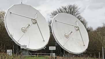
Two parabolic reflectors used for commercial / research applications
The parabolic reflector antenna or dish antenna is known for its distinctive shape, its high gain, and narrow beamwidths. It is the performance which can be achieved by using one is the reason it is so widely used at higher frequencies.
In view of its operation, these antennas are generally used for UHF, microwave and millimetre wave operation.
Parabolic reflector basics
The parabolic reflector or dish antenna is relatively straightforward in its basic concept, although the actual operation and optimisation can be a little more involved.
When lookking at how this type of antenna works, it cna be split into its basic constituents, and these show how the antenna operations, and how some different configurations arise.
There are two main elements to any parabolic reflector antenna:
Radiating system: The radiating element within the parabolic reflector antenna can take a variety of forms. In some antennas it may be a simple dipole, in others a horn. Its aim is to illuminate the second element of the antenna, the reflector with an even density of radiation with the minimum spillage or radiation missing the reflector and being radiated elsewhere.
Reflector: The reflector is the distinctive part of the parabolic reflector antenna. The parabolic shape is key to the operation of the RF antenna because the paths taken from the feed point at the focus to the reflector and then outwards are in parallel. However more importantly the paths taken are all the same length and therefore the outgoing waveform will form a plane wave and the energy taken by all paths will all be in phase. This enables the antenna to perform in a particularly effective manner.
The parabolic shape of the reflector surface of the antenna enables a very accurate beam to be obtained. In this way, the feed system forms the actual radiating section of the antenna, and the reflecting parabolic surface is purely passive.
When looking at parabolic reflector antenna systems there are a number of parameters and terms that are of importance:
Focus The focus or focal point of the parabolic reflector is the point at which any incoming signals are concentrated. When radiating from this point the signals will be reflected by the reflecting surface and travel in a parallel beam and to provide the required gain and beamwidth.
Vertex This is the innermost point at the centre of the parabolic reflector.
Focal length The focal length of a parabolic antenna is the distance from its focus to its vertex.
Aperture The aperture of a parabolic reflector is what may be termed its "opening" or the area which it covers. For a circular reflector, this is described by its diameter. It can be likened to the aperture of an optical lens.
Gain: The gain of the parabolic reflector is one of the key parameters and it depends on a number of factors including the diameter of the dish, wavelength and other factors.
Feed systems: The parabolic reflector or dish antenna can be fed in a variety of ways. Axial or front feed, off axis, Cassegrain, and Gregorian are the four main methods.
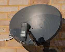
For most domestic systems like those used for satellite television reception, a small reflector combined with a focal point feed are used, providing the simplest and most economical form of construction.
These antennas may not always look exactly like the traditional full dish antenna. For mechanical and production reasons the feed is often offset from the centre and a portion of the paraboloid used, again offset from the centre as this provides mechanical advantage.
When selecting the type of antenna to be used for any given application, it is always necessary to look at the characteristics for that type of antenna. The parabolic reflector has both advantages and disadvantages. These make it suitable for use in some applications but not in others.
Advantages:
Some of the major advantages of the parabolic reflector antenna include the following:
High gain: Parabolic reflector antennas are able to provide very high levels of gain. The larger the 'dish' in terms of wavelengths, the higher the gain.
High directivity: As with the gain, so too the parabolic reflector or dish antenna is able to provide high levels of directivity. The higher the gain, the narrower the beamwidth. This can be a significant advantage in applications where the power is only required to be directed over a small area. This can prevent it, for example causing interference to other users, and this is important when communicating with satellites because it enables satellites using the same frequency bands to be separated by distance or more particularly by angle at the antenna.
Disadvantages:
Like all forms of antenna, the parabolic reflector has its limitations and drawbacks:
Requires reflector and drive element: the parabolic reflector itself is only part of the antenna. It requires a feed system to be placed at the focus of the parabolic reflector.
Cost : The antenna needs to be manufactured with care. A paraboloid is needed to reflect the radio signals which must be made carefully. In addition to this a feed system is also required. This can add cost to the system
Size: The antenna is not as small as some types of antenna, although many used for satellite television reception are quite compact.
Parabolic reflector antenna applications
There are many areas in which the parabolic dish antenna is used. In some areas it is the form of antenna that is used virtually exclusively because of its characteristics.
Direct broadcast television: Direct broadcast or satellite television has become a major form of distribution for television content. The wide and controllable coverage areas available combined with the much larger bandwidths enable more channels to be broadcast and this makes satellite television very attractive.
Domestic satellite television parabolic reflector antenna showing the offset feed arrangement to reduce aperture block which reduces the antenna gain.
The drawback is that satellites cannot broadcast very high power levels and combined with the path loss from geostationary orbit the signal levels are low. This means that directive antennas must be used to provide sufficient gain while being able to receive signals from only one satellite – several satellites could be visible from one location and broadcasting on the same frequencies. The parabolic reflector antenna is able to meet these requirements and has the added advantage that it would not be as long as a Yagi for an equivalent level of gain and directivity.
Microwave links: Terrestrial microwave links are used for many applications. Often they are used for terrestrial telecommunications infrastructure links. One of the major areas where they are used these days is to provide the backhaul for mobile telecommunications systems.
A variety of microwave parabolic reflector antennas mounted on a mobile phone tower
Satellite communications: Many satellite uplinks, or those for communication satellites require high levels of gain to ensure the optimum signal conditions and that transmitted power from the ground does not affect other satellites in close angular proximity. Again the ideal antenna for most applications is the parabolic reflector antenna.
Radio astronomy: Radio astronomy is an area where very high levels of gain and directivity are required. Accordingly the parabolic reflector antenna is an ideal choice.
In all these applications very high levels of gain are required to receive the incoming signals that are often at a very low level. For transmitting this type of RF antenna design is able to concentrate the available radiated power into a narrow beamwidth, ensuring all the available power is radiated in the required direction.