
What is a Balun: RF Antenna Balun
Baluns are used in many areas to transition between balanced & unbalanced scenarios: one key area is for radio frequency, RF applications for antennas.
RF Antenna Baluns & Ununs Includes:
Antenna Balun basics
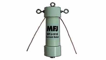
Current balun
Unun basics
RF baluns are used with many antennas and their feeders to transform a balanced feed or line to an unbalanced one.
There are issues when a balanced antenna such as a dipole or similar form of antenna is directly fed with an unbalanced feeder like coax.
Coaxial feeder has many advantages over balanced feeder when it comes to use at VHF and above and also when routing the feeder though a building, or near other objects.
In order to obtain the best overall performance and convenience, it is necessary to convert the balanced feeder or antenna feed point to an unbalanced system using a balun.
What is a balun: definition
Baluns are widely used with antennas and antenna system for radio communications, broadcast and many other applications. They enable the best performance to be obtained from many forms of antenna.
It is useful to define exactly what a balun is.
Balun definition:
A balun: balanced to unbalanced is an electrical device that converts between a balanced signal and an unbalanced signal, or feed line. A balun can take many forms and may include devices that also transform impedances but need not do so.
Although widely used with RF antennas, baluns may also be used in a variety of applications including: power line communications; data communications converting between Cat 5, Cat 6, etc and Twinax; video where a conversion between a twisted pair and a coaxial cable, etc. There are many other uses for baluns, but these are some of the main ones.
For use with RF antennas, baluns are needed where a balanced antenna such as a dipole is used. The most convenient form of feeder to use is coaxial cable as this can be routed far more conveniently along antenna towers, or poles, along the ground and through buildings, etc without the need to worry about affecting the coax cable performance.
Balanced feeder is very good, normally having very low levels of loss, but its operation relies on the fact that there are equal and opposite currents flowing in the two wires which enables the fields to cancel and the signal to be transferred with very low loss. Nearby objects cause the balance to be impaired, and loss levels to rise as a result of radiation of the signal, as well as levels of spurious pick-up along the cable to increase which can give rise to unwanted interference.

To enable the transition to be made between a balanced antenna feed point, or a balanced feeder and an unbalanced feeder such as coaxial cable, a balun is required.
One of the main forms of antenna that is balanced is a dipole antenna. This form of radio antenna is used in many radio communications applications on its own as well as within other forms of antenna such as a Yagi (Yagi-Uda) antenna, and many other types of radio antenna. In order for these balanced antennas to be fed by coaxial cable, an antenna balun is often included at the feed point.

There are several reasons why baluns may be needed for an antenna system:
Prevent radiation / pickup from coax outer conductor: If a balanced antenna is used and fed directly using coaxial feeder, then it is found that the outer or shield of the coax can radiate and pick-up radio frequency signals. For receiving, this can mean that interference from electrical apparatus, etc within the home, building, or just close to the feeder can be picked up. For transmitting, it can mean that the feeder will radiate signal which could cause interference and result in feeder loss.
Using a balun ensures that the coaxial feeder operates in the correct manner and the best overall performance for the antenna system is achieved.
Sometimes it is possible to get away without using a balun. Often one tell-tale sign is if the VSWR of the antenna system changes if the feeder is moved or touched, but in reality the only real way to tell if a balun is needed is to measure the common mode currents on the feed-line.
Where radiation pattern of the antenna is important: If radiation or pickup occurs from the outer conductor of the unbalanced cable (coax feeder), then this will affect the overall radiation pattern of the antenna. In cases where this is important, e.g. when making radiation pattern tests, it is important that radiation and pickup only occur from the antenna. In these cases a balun is essential.
Where radiation close to the transmitter must be minimised: If some of the radio frequency signal intended for radiation from the antenna is also radiated from the feeder, then there will be higher levels of RF around the transmitter. This can impact the transmission in a variety of ways. It can disrupt data mode transmissions when RF gets onto the interface between the transmitter and the computer causing the system to fail. If analogue audio transmissions are being used then it can get onto the audio input lines and cause strange feedback effects. The solution to issues like this can be to use a balun at the balanced to unbalanced transition. Even if the issue is not cured, it is most likely to improve the situation.
Balun basics
The basic concept of a balun is normally to use a transformer. Although there are many different types of balun, the basic transformer type is a good place to start to illustrate the basic operation.
The concept of a balun is based around a transformer, and its main function as a balun is to isolate the direct connection between the balanced antenna or feeder and the unbalanced coaxial feeder. In this way, the earth connection for the unbalanced cable is not directly connected to the balanced system, and it remains balanced.
All transformers have a limited bandwidth, so the bandwidth of the balun must be designed to be greater than that of the antenna or other system with which it will be used.
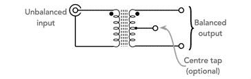
The most obvious method of creating a balun is to create a transformer with two windings - one side is grounded, and the other side has differential outputs. It is possible to ground a centre tap on the balun if needed, but for antenna systems this is not normally done.
It is also worth noting that the balun is bi-directional, there is no input or output as such, only balanced and unbalanced sets of terminations.

Current & voltage baluns
There are two main classes of baluns that can be realised:
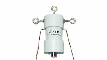
Current balun: the current balun forces equal current through the two sides of a balanced load. The 1:1 current balun is effectively a simple transmission line such as a bifilar winding or coaxial cable wound on a ferrite core.
Voltage balun: The voltage balun forces equal voltage across the two sides of a balanced load. Voltage baluns are a little more complicated than current baluns and prove to be very inefficient in preventing the coaxial cable shield as well as open ladder line to carry common mode currents and radiate energy. Accordingly voltage baluns are not used for most antenna applications.
Types of antenna balun
Although the essence of many baluns is a transformer, there are several different types of balun that can be used. Some employ different circuit techniques, while others use different concepts. However all form the basic function of changing from a balanced to unbalanced system.
Classical transformer balun: The traditional approach for a balun is to use a transformer. This consists of two electrically separate windings, normally wound on a core - typically a toroidal ferrite core. Having two separate windings in this fashion means that the two circuits are electrically isolated which can have advantages for some applications.
Transformer antenna balun The core on which the transformer is wound can either be an air core, generally with a former which may be porcelain to keep the two coils in place, or it can be made from a magnetic conductor like ferrite. The ferrite needs to be chosen so that it can handle the frequencies and power levels involved.
The ratio of the turns between the primary and secondary, determines the ratio of the input and output impedance levels. It is therefore possible to not only use the balun to convert between balanced and unbalanced, but to also act as a matching transformer if needed. This can be very useful where the antenna or other feeder has a high impedance levels that needs to be converted down to a lower level for use with standard 50Ω coax, etc . . In some instances it may be necessary to step the impedance up for the coaxial feeder.
It should also be remembered that there will be losses in the balun. Although these are normally small, they still need to be considered in some applications.
One issue with this form of balun is that the two halves are totally electrically isolated. It is found that external antennas can pick up static and a charge can build up. To overcome this, a balun with a centre tap on the balanced winding can be used. The centre tap is taken to earth to dissipate the charge.
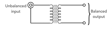
Auto-transformer balun: As the name implies, this form of balun uses an auto-transformer, i.e. a single winding, to provide the balanced to unbalanced transition.
Autotransformer antenna balun One of the advantages of the auto-transformer style of balun is that it inherently provides a DC path to ground for all connections, both at the unbalanced coaxial input, and also for the balanced input as well. As described above, this enables static to be discharged.
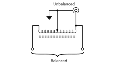
RF choke as a balun: One of the main issues with feeding a balanced antenna with an unbalanced feeder like coax, is that RF travels along the outer of the coax and this can result in unwanted radiation and pickup.
The concept of the choke balun is to increase the inductance on the outer conductor of the unbalanced conductor to prevent signals travelling only along this conductor.
One implementation of a choke balun is to coil a few turns of feeder up at the feed-point of the antenna to act as a feed-line choke. Although a very easy implementation, it does not always work well. The common mode rejection ratio of a balun depends on the impedance of the system at the point that the balun is used. Also, the inductance of a few turns of coax may not be sufficient to provide adequate rejection at frequencies below 10 MHz or so.
Another implementation is to wind the coax around a toroidal former. Obviously the bend radius of the coax needs to be considered and this means that larger toroids are generally required. The properties of the toroid ferrite also need to be considered to provide the best attenuation at the frequencies of use.
Mounting a balun
Although baluns take many forms, they are often used with external antennas and require the mechanical arrangements to be addressed as well.
There are a number of factors to be considered:
Weather protection: As many baluns are used externally they should be made in a fashion that will be able to withstand the rigours of the weather. Heat, sun, rain, freezing temperatures and more all take a toll on any item in a remote position. Whilst water ingress is a major issue which may allow damp to enter any coaxial feeder, sun can also cause plastics to degrade over time, heat can cause any box sealing or other sealing to degrade, and freezing temperatures may also cause degradation.
Any coaxial cable should be adequately sealed, possibly by covering any connector using self-amalgamating tape, etc.
Mechanical fixings: It is important that any balun can be mechanically incorporated into the antenna system. If the balun interfaces between coax cable and ladder line, it may not need any additional methods of holding it in place. However, many baluns also form the centre or "T" piece for a wire dipole antenna, for example for HF wire antennas.
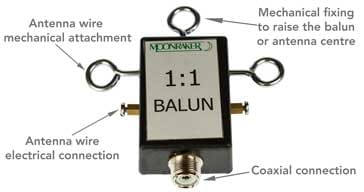
Typical HF antenna balun Here the tension the wire should not be held by the connections. Instead there should be some form of strain relief incorporated into the balun, or a dipole "t" piece used and the balun attached to the centre piece with looped wires to the balun connections. It also often helps to have a fixing for the centre support. This is particularly useful when the balun is used with an inverted V dipole, where the centre of the dipole is fixed to a centre high pole, mast or other fixing point.
Baluns are an essential element in many antenna systems. They enable a balanced antenna or feeder to be transitioned correctly to an unbalanced one like coax that can easily be routed through a building, etc to where it is needed.
Baluns can take many forms, and this enables the most suitable format to be adopted for any particular situation.
More Antenna & Propagation Topics:
EM waves
Radio propagation
Ionospheric propagation
Ground wave
Meteor scatter
Tropospheric propagation
Antenna basics
Cubical quad
Dipole
Discone
Ferrite rod
Log periodic antenna
Parabolic reflector antenna
Phased array antennas
Vertical antennas
Yagi
Antenna grounding
Installation guidelines
TV antennas
Coax cable
Waveguide
VSWR
Antenna baluns
MIMO
Return to Antennas & Propagation menu . . .

