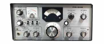
Yaesu Sommerkamp FR-50B
Designed and manufactured by Yaesu, the FR-50B HF amateur bands communications receiver was sold globally from around 1967, but in Europe it was branded with the Sommerkamp name.
Yaesu Equipment Includes:
Yaesu / Sommerkamp FR-50B
Iconic radio receivers:
Summary of iconic radio receivers
Radio receiver history
Crystal radio sets
Development of the superhet radio
Radio history / timeline
The Yaesu FR-50B was an amateur bands only HF communications receiver. The radio was marketed under the Sommerkamp name in Europe as they were the sole importers for Europe.
The FR50B covered the amateur bands of the time from 80 metres up to 10 metres, and it used a double conversion superhet design using a crystal controlled second conversion.
The FR50B was a hybrid design using both valves or vacuum tubes as well as a few transistors. As such it gave an indication of the fact that transistors could be used in performance equipment.
At the time, transistor technology and circuit techniques were not sufficiently advanced to enable the very high performance levels of valves, especially in terms of spurious signals, overload performance and the like.
FR-50B development
The FR-50B was one of Yaesu's early products as it started to gain a foothold in the global amateur radio market.
Yaesu launched its first amateur radio products around 1960 with some SSB generator boards that could built in to transmitters.
In 1962 they launched their first domestic transmitter and this was followed in the coming years with other transmitters and receivers.
Then, in 1967 they launched the FR-50 receiver and upgraded this a couple of years later with the FR-50B.
As Yaesu did not have a large marketing and sales department, they entered into an agreement with the Swiss company Sommerkamp to sell their equipment in Europe, and this was done under the Sommerkamp brand name - all equipment was branded Sommerkamp rather than Yaesu.
Yaesu FR-50B specifications
The Yaesu FR-50B provided a good level of performance, but it tended to be at the more budget end of the market, and so its performance did not compete with items like the Collins S line and the like.
| Yaesu FR-50B Communications Receiver Performance Summary |
|
|---|---|
| Parameter | Details |
| FR-50B summary | Double conversion HF amateur radio band double conversion superheteroheterodyne radio with VFO controlled first conversion and crystal controlled second conversion. |
| Frequency bands (standard) |
80m: 3.5 - 3.8 Mc/s 40m: 7.0 - 7.5 Mc/s 20m: 14.0 - 14.5 Mc/s 15m 21.0 - 21.5 Mc/s 10m: 28.0 - 29.2 Mc/s JJY & WWV: 10 - 10.5 Mc/s |
| Sensitivity | SSB / CW: Less than 0.5µV for 10dB S/N AM Less than 1µV for 10 dB S/N |
| Selectivity | ± 1.8 kc/s @ -6dB ± 5 kc/s at -50dB |
| Image ratio | Better than 50dB |
| Intermediate frequencies | 1st IF: 5173.9 Kc/s 2nd IF: 455 kc/s |
| Calibrator | 100 kc/s crystal calibrator option available |
| Audio output | 1.5 watts 4Ω / 600Ω built in speaker |
| Power | 100V AC 50/60 c/s 50VA (220 or 240 VAC available for export models). |
| Dimensions (inches) | 13 wide, 6 high, 10¼ deep |
| Weight | Approx 17½ lbs |
FR-50B circuit description
In many respects the FR-50B followed a relatively well proven path in the topology that the design team followed. The receiver used a double conversion technique, but it used a VFO controlled first oscillator and crystal controlled second oscillator.

This approach reduced costs when compared to the receivers that adopted a crystal controlled first conversion approach, while still giving the improved image rejection that was obtained by using a higher first IF at 5173.9kc/s, and the selectivity afforded by the lower second IF at 455kc/s.
However the receiver did incorporate a number of transistors in the design. Although the main line-up used the traditional valves, the VFO used for the first local oscillator, its buffer and the crystal oscillator for the second conversion all used transistors.
At this time the performance of all transistor radios was not equal to that which could be obtained using valves / tubes, especially in terms of spurious signals, overload performance and general dynamic range. As a result transistors were used in positions where they could provide some advantages in terms of performance.
The set used a total of eight valves / tubes and three transistors for the main receiver circuitry.
| Valve Line-up for Yaesu FR-50B Communications Receiver |
||
|---|---|---|
| Valve Number | Type | Use within the circuit |
| V1 | 6BZ6 | RF amplifier |
| V2 | 12AT7 double triode | 1st mixer & optional crystal calibrator |
| V3 | 6CB6 | Second mixer |
| V4 | 6BA6 | Second IF amplifier (455kc/s) |
| V5 | 6BA6 | Second IF amplifier (455kc/s) |
| V6 | 6BE6 | Product detector |
| V7 | 6BA6 | Beat frequency oscillator |
| V8 | 6BM8 | Audio amplifier |
The FR-50B not only used valves / tubes, but it also had a number of transistors in the circuit as well.
| Semiconductor Line-up for Yaesu FR-50B Communications Receiver |
||
|---|---|---|
| Transistor Type Number | Type | Use within the circuit |
| TR1 | 2SC372 (Silicon NPN) | VFO oscillator |
| TR2 | 2SC372 (Silicon NPN) | VFO buffer |
| TR3 | 2SC372 (Silicon NPN) | Second conversion oscillator (crystal controlled oscillator) |
The receiver is relatively straightforward in terms of its circuit and overall block diagram. The signal follows through the block diagram in the standard fashion.
RF amplifier: The RF amplifier input stage was based around a high Gm 6BZ6 valve / tube. Using this valve / tube, it provides high overload capability and hence low levels of intermodulation and cross modulation. This is ideal for bands where very strong signals were present such as the 40 metre band where high power broadcast stations were very close to the amateur radio stations. The 6BZ6 also enables an excellent AGC characteristic to be obtained.
In addition to this, the RF amplifier incorporates a 5MHz trap to prevent any signals from the antenna entering the second IF stage. This is, of course, in addition to the normal RF tuning that is present on this stage.
Also present in this circuit is a pre-selector tuning capacitor that enables the RF tuning to be optimised for the particular antenna and position in the band.
1st mixer : The signal from the RF amplifier is passed to the first mixer and it is mixed or multiplied with the signal from the 1st local oscillator. A triode is used for this stage, introducing the two signals onto the grid and cathode of the circuit.
The output is at 5173.9 kc/s and the anode of the mixer is tuned to this frequency and the signal then passed along to the next stage.
Variable frequency oscillator: An LC tuned free running variable frequency oscillator was used to provide the first local oscillator signal. The circuit was based around a 2SC372 silicon NPN transistor with an ft of 80MHz.
The circuit used a Colpitts configuration and the band switch selected the required coil / capacitor combinations. The LC combinations used temperature compensating capacitors to ensure the optimum frequency stability, even for the 28 Mc/s band. Even though the VFO had compensation capacitors a free running VFO, especially one that had switched elements in it would never be particularly stable, especially by today's standards and drift would always be a problem, although it was normal for many receivers of this era.
The output from the oscillator circuit was passed to an emitter follower buffer circuit, again based around a 2SC372 NPN transistor. The output from this was injected into the grid of the first mixer.
The output from the buffer was also made available externally so that it could be used as the VFO source for compatible transmitters, allowing transceiver capability.
1st IF stage: This stage effectively consists of the tuned coupling transformer between the first and second mixers. This provides sufficient filtering to remove any unwanted mix products. The adjacent channel filtering is provided by the second IF stage.
2nd mixer: The output of the 1st IF and the 2nd local oscillator are applied to the control grid of V3, a 6CB6 valve / tube. The output is taken from the anode of this valve via a tuned IF transformer to give the 455 kc/s IF signal for further amplification and filtering.
2nd local oscillator: The third transistor in the line up, TR3 is used as the crystal controlled oscillator operating at 5628.9 kc/s to enable the second conversion to convert the signal from 5173.9 kc/s to 455 kc/s. The transistor and other components for the oscillator are all contained within an IF transformer case - the size reduction provided by the use of transistors as opposed to valves / tubes was starting to be reflected in the ways transistor circuits were being manufactured and used.
2nd IF amplifier: The second IF amplifier operating at 455 kc/s consisted of a two stage circuit using two 6BA6 valves / tubes.
The adjacent channel filtering was provided by two 4kc/s mechanical filters employed in the circuit
The signal strength "S" meter was added tot he cathode circuit of the first 6BA6 circuit. It needed adjusting for zero deflection when no signal was present. It indicated the cathode voltage variation of V4 which was proportional to the AGC voltage.
The cathode return of V5, the second 6BA6, was connected to that of the RF amplifier and to a potentiometer used to provide the RF gain.
AM detector & noise limiter: The AM detector circuit uses a single 1S1007 diode acting as an envelope detector for AM. A noise limiter is also included to reduce the effect of very loud crashes of pulse coming through the receiver. The circuit is based around a silicon diode and it may be switched out of circuit using a front panel control.
SSB and CW detection: The reception of single sideband and CW (Morse) was achieved using a beat frequency oscillator based around V7, a 6BA6 valve, and a mixer for the product detector itself using V6, a 6BE6. A BFO pitch control was incorporated to enable the BFO frequency to be trimmed to the required frequency for the mode and prevailing reception conditions.
Audio stages: The audio stages used a triode pentode 6AW8 valve. The triode section took the audio from the demodulator / detector in use and provided the audio pre-amplification. The pentode output section provided sufficient level to drive a 4 - 8 Ω loudspeaker via a transformer and there was also provision for a 600Ω output for headphones.
The circuit for the FR-50B worked well and followed a well tested and tried formula, although some semiconductor technology was introduced to improve the performance of some of the oscillators.
A number of these radios have survived the years since they were first introduced and can be seen at vintage radio sales and the like. Although now very dated and their performance is well down on what would be expected by a modern radio in terms of coverage, frequency stability, selectivity and the like, they can still be used
More History:
Radio history timeline
History of the radio
Ham radio history
Coherer
Crystal radio
Magnetic detector
Spark transmitter
Morse telegraph
Valve / tube history
PN junction diode invention
Transistor
Integrated circuit
Quartz crystals
Classic radios
Mobile telecoms history
Vintage mobile phones
Return to History menu . . .