
What is a Logic Analyzer
Logic analyzers are widely used to develop and debug electronic logic circuits - they display traces of multiple logic channels and reveal the circuit operation.
Logic Analyzer Includes:
Logic analyzer basics
How to use a logic analyzer
Logic analyzer specifications
Probes
Logic analyzers are test instruments that are widely used for testing complex digital or logic circuits. They meet the need for users who need to be able to investigate and understand the operation of these circuits.
Oscilloscopes can perform many of the functions of a logic analyser but the the logic analyzer is able to display relative timing of a large number of signals. Essentially a logic analyser enables traces of logic signals to be seen in such a way that the operation of several lines in a digital circuit can be monitored and investigated.
However many oscilloscopes are now able to incorporate many logic analyzer functions in what may be termed a mixed signal oscilloscope.
Logic analysers come in a variety of formats. Although it is possible to obtain those that use a traditional test equipment case, many more are now linked to computers and in this way have much greater levels of flexibility and processing power.
Logic analyser development
The first logic analysers were developed out of the need to be able de-bug and undertake fault-finding on microprocessor based systems.
In the early 1980s when these chips first started to become widely used, the urgent need arose to develop techniques that would enable the many lines and test points to be monitored simultaneously. Existing oscilloscopes were not able to provide the required levels of functionality.
After the early introduction of the first analysers, their complexity increased in line with the complexity of the circuits being tested. The number of channels grew, their speeds rose and the functionality in areas such as triggering improved greatly.
Logic analyser characteristics
There are several key characteristics of a logic analyser that separate it from multi-channel oscilloscopes and other test instruments:
- Multiple channels: Logic analyzers are designed to monitor a large number of digital lines. As logic analyzers are optimised for monitoring a large number of digital circuits, typically they may have anywhere between about 32 and 200+ channels they can monitor, each channel monitoring one digital line. However some specialised logic analyzers are suitably scaled to be able to handle many more lines, and in this way enable tracking and fault finding on much more complex systems.
- Provide a time display of logic states: Logic analysers possess a horizontal time axis and a vertical axis to indicate a logic high or low states. In this way a picture of the digital lines can be easily displayed.
- Displays logic states: The vertical display on the analyser displays the logic state as a high of low state. The signals enter the various channels and are converted into a high or low state for further processing within the analyser. It provides a logic timing diagram of the various lines being monitored.
- Does NOT display analogue information : These test instruments do not present any analogue information, and in this way they differ from an oscilloscope. They are purely aimed at monitoring the logic operation of the system. If any analogue information is required, then an oscilloscope must be used in addition.
Logic Analyzer vs oscilloscope comparison
Oscilloscopes and logic analysers are very different test instruments. While both have a very similar form of display, i.e. displaying waveforms, they use fundamentally different operational concepts.
| Comparison of Oscilloscope and Logic Analyzer | |
|---|---|
| Logic Analyzer | Oscilloscope |
|
A logic analyser is used for verifying and debugging the operation of digital designs looking a logic states and timings.
|
Oscilloscope is used for measuring analogue waveforms: amplitude, phase values, or edge measurements such as rise times, etc.
|
Logic analyser types
Although development of these test instruments is on-going and new variants are constantly being launched and many technology innovations are being achieved, there are some main categories into which most logic analyzers can be split:
- Modular logic analyzers : This type of logic analyser is probably what may be thought of as the most typical form of test instrument, although it is the highest cost option providing the highest level of functionality. It comprises a chassis and the various modules - including channel modules. The number of modules being larger for the higher channel counts.
- Portable logic analyzers : In a number of instances there may be a need for a smaller analyser, possibly for restricted budgets or for field service. These test instruments incorporate all elements of the analyser into a single box for ease of transportation.
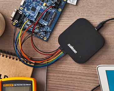
- PC based logic analyzers: There is a growing number of PC based logic analysers. These consist of an analyser unit that is connected to a PC. USB is an obvious option for this, but Ethernet is also widely used because of its high speed. This form of PC based instrument uses the processing power of the PC combined with its display to reduce the cost of the overall system. For the future it is likely that PC based logic analyzers and in particular USB logic analyzers will be used increasingly, especially as the cost of USB analyzers can be much lower than other forms, and they can offer high levels of performance using the power of the associated computer..
Logic analyzer applications
The main use for logic analyzers is to look at digital signals. They were a particularly attractive and useful test instrument many years ago when complicated digital systems were made using many different ICs. It was possible to gain access to the various test points and it was possible to debug the wide busses and IO. Now with much higher levels of integration this is not always possible because there are more embedded devices using System On a Chip, SOC designs, and access to the required test points is not achievable.
Despite this there are still many potential measurements for a logic analyzer, particularly for use with the many board computer systems like the Arduino, Raspberry Pi and many others.
Using a logic analyzer it is possible to time correlate a large number of signals on a single display. This can be sued to gain a good viw other data movement and processing within many embedded systems or within the peripherals of small computer systems.
One example of an application is to monitor the data comes into a microprocessor UART and then back out to an SPI device, perhaps EEPROM, and then finally a piece of data out to an I2C device. Using a logic analyzer it is possible to view all of these buses over an extended period and this would not be viable on an oscilloscope.
As a result logic analyzers from the simple maker / hobbyist low cost USB logic analyzer versions right up to professional development systems are all useful in their different arenas.
Logic analyzers are an important form of test instrumentation. They enable engineers and developers to see exactly what is happening within logic circuits. Looking at the logic signals on a variety of lines they are able to provide a much better level of insight into the operation of logic circuits than other forms of test instrumentation.
More Test Topics:
Data network analyzer
Digital Multimeter
Frequency counter
Oscilloscope
Signal generators
Spectrum analyzer
LCR meter
Dip meter, GDO
Logic analyzer
RF power meter
RF signal generator
Logic probe
PAT testing & testers
Time domain reflectometer
Vector network analyzer
PXI
GPIB
Boundary scan / JTAG
Data acquisition
Return to Test menu . . .

