
Understand the Logic Probe & How to Use One
Logic probes are cheap and easy to use digital testers- understand what they are, how they work, how to use them & discover some top hints & tips.
Logic Probe Tutorial Includes:
Logic probe basics
Logic probes are very cheap and easy to use as simple digital testers in many applications. Logic probes can provide a simple way of testing slow moving digital logic levels and signals.
Being very cheap to buy, these digital logic probes are ideal for experimenters, but they will seldom be found in a professional electronics laboratory because of their limited measurement capability and the availability of more advanced test equipment, like logic probes or mixed signal oscilloscopes or other forms of electronic test equipment.
What is a logic probe?
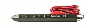
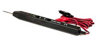
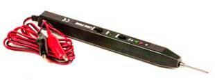
The logic probe or digital tester is normally a low cost handheld probe contained within a pen-like tube with indicator lights to show the state of the line being probed.
Typically logic probes are used to test digital circuits like those using TTL or CMOS logic. They often have three indicator lights on the body to indicate the state of the line. As such logic probes are very basic forms of digital testers, only able to test the state of a single line, but they can be useful in many applications.
The logic probe is normally powered by the circuit under test - there are normally leads with crocodile / alligator clips that can be attached to the ground and supply of the circuit under test.
Logic probe measurements
A logic probe is restricted in the number of measurements it can make when compared to other test instruments, but it can nevertheless be used for a variety of digital measurements:
- Logic high state: The logic probe / digital logic tester is able to detect lines that are at the digital or logic high state. The logic probe will indicate this typically with an LED which is often coloured red.
- Logic low: The logic probe also is able to indicate a logic or digital low. A common indication is with the use of a green coloured LED.
- Digital pulses: The logic probe may incorporate some form of pulse detection circuitry. When the line is active and being pulsed a third colour, possibly amber will be indicated. The logic probe may well incorporate circuitry to detect very short pulses and in this way indicate when the line is active. Sometimes the length of the pulses may be indicated by the brightness of the LED.
- Line tri-stated: Some logic probes may also be able to detect when a line has been put into a tristate option. This is when the output device has its output turned off and no real logical state is defined. Many logic probes are able to indicate this state and they may do this by having all indicators turned off.
Logic probes vary from one manufacturer the next and therefore it is necessary to check exactly what measurements can be made and how the results are indicated.
Advantages and disadvantages of a logic probe
As with any item of test equipment, there are advantages and disadvantages to the use of a logic probe tester than need to be considered before buying or using one.
Logic probe advantages -
- Low cost: A logic probe does not contain much circuitry, and the display is very rudimentary. Therefore the cost of manufacture is very low – they can typically be bought for less than the cost of a very basic multimeter. Logic analyzers and mixed signal oscilloscopes cost very many times more than logic probes.
- Ease of use : To use a logic probe typically requires the connection of power leads and then connecting the probe to the required point on the circuit.
Logic probe disadvantages -
- Very rough measurement: The nature of the logic probe means that only an indication of the presence of a logic signal can be detected. It is not replacement for a test instrument such as an oscilloscope.
- Poor display: A logic probe only uses a few LEDs to indicate the nature of the logic signal. As a result, little information can be displayed about the nature of the logic signal that is detected.
A logic probe tester is a very cheap and simple item of test equipment. It is able to provide a quick but very basic test for many logic circuits. However it is not nearly as flexible as an oscilloscope or a logic analyzer.
A logic probe can be used for quick testing, whereas for more in-depth testing more sophisticated test equipment is needed. It should be remembered that it is not suitable for many high speed logic circuits. It typically will only be useful for basic tests on basic circuits.
Logic probe typical specifications
While all models of logic probe will vary slightly, it is possible to provide some outline of the typical specifications for a probe.
Generally logic probes are aimed at a basic test only and therefore offer a relatively basic level of performance. Nevertheless they can be invaluable in locating faults in many situations.
A typical specification may be:
| Typical logic probe specifications | |
|---|---|
| Parameter | Specification |
| Logic 1 Signal input level |
TTL: > 2.3V ±0.02V CMOS: > 70% Vcc ± 10% |
| Logic 0 Signal input level |
TTL: < 0.08V ±0.02V CMOS: < 30% Vcc ± 10% |
| Max supply voltage withstand | 20 V |
| Power supply range | 5 - 15 V |
| Signal input impedance | 1 MΩ |
| Max input signal frequency | 20 MHz |
| Minimum detectable pulse width | 30 ns |
The specifications will vary from one logic probe tester to the next, but they give the rough ideal of the performance that might be expected. Some higher performance probes are available with higher frequency capabilities and the ability to detect shorter pulses, but they cost more than some of the lower cost test instruments.
The logic probe can be a very useful simple tester and save the cost of more expensive forms of electronic test equipment having to be bought. If thier limitations are understood, then they can prove to be very useful in many instances with simple electronic circuits.
How to use a logic probe: the basics
Understanding how to use a logic probe is very straightforward. There are many different logic probe products, all of which are slightly different, but they all conform to the same basic overview of their functionality and operation, for example some have audible indications as well as the visual ones whereas others may not.
Accordingly it is possible to give some basic guidelines about how to use a logic probe, but there will be slight variation in the way they are used dependent upon the particular logic probe in use.
• Logic probe connections
Before using the logic probe, it is necessary to understand the connections.
As can be seen, there are three connections to the logic probe:
- Black lead with crocodile clip: There are two leads which generally come out of the opposite end of the instrument to the metal probe itself. The black lead is connected to negative ground and is also used as the return.
- Red lead with crocodile clip: This lead will have red on it somewhere, possibly just on the crocodile / alligator clip and is used to connect to the supply. Be careful to connect this to the logic supply which will normally be +5 volts and for some CMOS families up to 15 volts. Read the instructions to see over what range the probe will operate - using a voltage higher than that which is specified could damage the logic probe.
- Probe: The probe, as shown on the diagram is a metal point used for probing the circuit. When using this, be careful that the probe cannot slip and cause a short circuit which could damage the circuit under test.
The first requirement before using the logic probe is to connect the power connections to the circuit. Apart from ensuring they are the right voltage, the points used for connecting the crocodile clips to should be accessible and provide a reliable connection without the risk of touching any adjacent components or other connections.
Note: If possible connect the power connections to the unit under test when it is powered off. In this way risk of damage due to shorting, etc. is minimised.

• Initial settings for using a logic probe
It is necessary to select the required settings on the switches when starting to use a logic probe. Dependent upon the logic probe manufacturer and model, there are a number of options that may need to be set:
- TTL / CMOS: It is necessary to select the logic family. Normally two options are given, namely CMOS and TTL. As the high and low states of these two logic families are slightly different, it is necessary to select the correct option. Normally logic probes will only accommodate the use of basic 5V versions of CMOS and TTL. Other families like the ones that use 3.3 volts or other rails are unlikely to be accommodated.
- MEM / PULSE : This is used to select the operational mode of the logic probe. The Pulse position is used for normal operation for pulse or level detection. The MEM or memory position is used to capture a pulse. For example if it is necessary to detect whether a pulse has occurred or not.
Note: Some surface mount devices these days use supply rails of 3.3 volts or less. Most logic probes will not work with these ICs as the logic levels cannot normally be accommodated. Additionally it is often difficult to probe surface mount boards as there is a real danger of shorting pins.
• Probing & results
With power applied to the circuit under test and the logic probe, it is possible to use it to probe various points on the circuit.
One easy point to locate may be a transistor driver. The can of the transistor is often connected to its collector making a point where the signal can be easily accessed.
The logic probe will indicate which lines are high, low or carrying a signal.
It is then a matter of interpreting the results in line with the circuit to find out whether they are acting correctly or not.
A brief order of using a logic probe could be:
- Connect the black clip or line to ground or to a common line of the circuit to be tested. This assumes that 0V and ground / common are the same.
- Secondly connect the red clip or leave to the positive supply of the circuit.
- Select the logic family CMOS or TTL. TTL normally runs using a 5V supply whereas CMOS is typically 5 - 15V.
- Use the probe to connect to the required monitoring points. At this point the LEDs will light accordingly and a buzzer if included may sound.
- Setting a MEM switch to MEM will enable the logic probe to capture any short pulses. There may be a separate LED to indicate this.
One hint is that it is often good to check how to use the logic probe on a known good circuit. In this way you will better understand its operation and know what to look for.
Whilst the logic probe is a very basic test tool, it can help find problems on many circuits if you know how to use the logic probe and understand its limitations.
Logic probes are very simple devices that are cheap and easy to use. Their performance is comparatively limited, as they cannot easily operate at high frequencies, but they can still be used to very good effect with low frequency or static logic levels.
Although their performance is limited, they can still be a very convenient test instrument to use in a variety of circumstances.
More Test Topics:
Data network analyzer
Digital Multimeter
Frequency counter
Oscilloscope
Signal generators
Spectrum analyzer
LCR meter
Dip meter, GDO
Logic analyzer
RF power meter
RF signal generator
Logic probe
PAT testing & testers
Time domain reflectometer
Vector network analyzer
PXI
GPIB
Boundary scan / JTAG
Data acquisition
Return to Test menu . . .

