
Simple LC High Pass Filter Circuit Design & Calculations
Design considerations, circuit and formulas for a basic 3 pole LC high pass filter for RF applications.
Constant K Filter Includes:
Constant-k filter
Simple LC LPF design
LC HPF design
LC band pass filter design
Filter basics includes::
RF filters - the basics
Filter specifications
RF filter design basics
High & low pass filter design
Constant-k filter
Butterworth filter
Chebychev filter
Bessel filter
Elliptical filter
High pass filters, and in particular LC high pass filters are used in many RF applications where they block the lower frequencies and allow through higher frequency signals.
Although not as widely used as low pass filters, high pass LC filters are used in many areas of RF design to remove unwanted signals and allow though the wanted ones.
Typically LC filters are used for the higher radio frequencies where active filters are not so manageable, and inductors more appropriate. Low frequency designs tend not to use inductors as active designs are more common, and inductors can become large and expensive.
High pass filter topologies
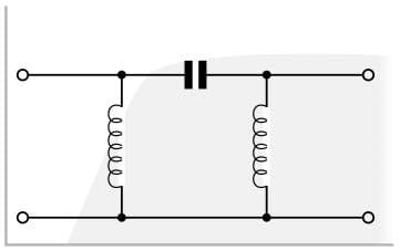
High pass filters using LC components, i.e. inductors and capacitors or even resistors and capacitors can be arranged in ether a pi or T network. As suggested by its name, the basic π network element has one series capacitor, and either side of it there is an inductor connected to ground. Further network elements can be cascaded if a faster roll off rate is required.

Similarly the T network high pass filter has one inductor to ground and either side there is a series in line capacitor. As with the π section network, further elements can be cascaded for improved roll off performance.

In this way these filters pass the high frequency signals, and reject the low frequency signals. These filters may be used in applications where there are unwanted signals in a band of frequencies below the cut-off frequency and it is necessary to pass the wanted signals in a band above the cut-off frequency of the filter.
High pass LC filter design
There is a variety of different filter variants that can be used dependent upon the requirements in terms of in band ripple, rate at which final roll off is achieved, etc. The type used here is the constant-k and this produces some manageable equations:
The π section can be calculated from the equations below and using the multipliers shown in the diagram, i.e. 2L and C.

The T section high pass filter can be designed using the equations below to calculate L and C, but note the diagram shows that this must be scaled as 2C and L are required for this design configuration.

The values for C and L using in the two LC high pass filter design configurations can be calculated from the equations below.
Where
Z0 = characteristic impedance in ohms
C = Capacitance in Farads
L = Inductance in Henries
fc = Cut off frequency in Hertz
Filter design & build precautions
There are a few guidelines, hints and tips that can be incorporated into the design and build of a high pass filter to ensure that it meets the requirements of the design and comes as close to the theoretical performance as possible.
- Cascading filter sections for better attenuation: In order to provide a greater slope or roll off in the high pass filter, it is possible to cascade several filter sections. When this is done the filter elements from adjacent sections may be combined. For example if two T section filters are cascaded and each T section has a 1 µH inductor in each leg of the T, these may be combined in the adjoining sections and a 2 µH inductor used.
- Use close tolerance components : The choice of components for any filter, and in this case for a high pass filter is important. Close tolerance components should be used to ensure that the required performance is obtained. It is also necessary to check on the temperature stability to ensure that the filter components do not vary significantly with temperature, thereby altering the performance.
- Filter layout: Care must be taken with the layout of the filter, especially when the filter is used for high frequencies. Capacitive and inductive coupling are the main elements that cause the filter performance to be degraded. Accordingly the input and output of the filter should be kept apart. Short leads and tracks should be used, Components from adjacent filter sections should be spaced apart. Screens used where required, and good quality connectors and coaxial cable used at the input and output if applicable.
This design provides an easy and manageable way to realise an LC high pass filter. Using the simple equations the design can be calculated and realised.
More Essential Radio Topics:
Radio Signals
Modulation types & techniques
Amplitude modulation
Frequency modulation
OFDM
RF mixing
Phase locked loops
Frequency synthesizers
Passive intermodulation
RF attenuators
RF filters
RF circulator
Radio receiver types
Superhet radio
Receiver selectivity
Receiver sensitivity
Receiver strong signal handling
Receiver dynamic range
Return to Radio topics menu . . .


