
What is QAM: quadrature amplitude modulation
QAM: Quadrature Amplitude Modulation combines amplitude & phase changes to give additional capacity & is widely used for data communications.
Quadrature Amplitude Modulation, QAM Tutorial Includes:
Quadrature amplitude modulation, QAM basics
QAM theory
QAM formats
QAM modulators & demodulators
Modulation formats:
Modulation types & techniques
Amplitude modulation
Frequency modulation
Phase modulation
Quadrature Amplitude Modulation, QAM utilises both amplitude and phase components to provide a form of modulation that is able to provide high levels of spectrum usage efficiency.
QAM, quadrature amplitude modulation has been used for some analogue transmissions including AM stereo transmissions, but it is for data applications where it has come into its own.
Quadrature amplitude modulation is able to provide a highly effective form of modulation for data and as such it is used in everything from cellular telecommunications systems to Wi-Fi and almost every other form of high speed data communications system.
What is QAM, quadrature amplitude modulation
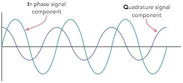
Quadrature Amplitude Modulation, QAM is a signal in which two carriers shifted in phase by 90 degrees (i.e. sine and cosine) are modulated and combined.
As a result of their 90° phase difference they are in quadrature and this gives rise to the name. Often one signal is called the In-phase or “I” signal, and the other is the quadrature or “Q” signal.
The resultant overall signal consisting of the combination of both I and Q carriers contains of both amplitude and phase variations. In view of the fact that both amplitude and phase variations are present it may also be considered as a mixture of amplitude and phase modulation.
A motivation for the use of quadrature amplitude modulation comes from the fact that a straight amplitude modulated signal, i.e. double sideband even with a suppressed carrier occupies twice the bandwidth of the modulating signal.
This is very wasteful of the available frequency spectrum. QAM restores the balance by placing two independent double sideband suppressed carrier signals in the same spectrum as one ordinary double sideband supressed carrier signal.
Analogue and digital QAM
Quadrature amplitude modulation, QAM may exist in what may be termed either analogue or digital formats. The analogue versions of QAM are typically used to allow multiple analogue signals to be carried on a single carrier.
For example it was used in the old PAL and NTSC television systems, where the different channels provided by QAM enabled it to carry the components of chroma or colour information.
In radio applications a system known as C-QUAM is used for AM stereo radio. Here the different channels enable the two channels required for stereo to be carried on the single carrier.
Digital formats of QAM are often referred to as "Quantised QAM" and they are being increasingly used for data communications often within radio communications systems.
Radio communications systems ranging from cellular technology as in the case of LTE through wireless systems including WiMAX, and Wi-Fi 802.11 use a variety of forms of QAM, and the use of QAM will only increase within the field of radio communications.
Digital / Quantised QAM basics
Quadrature amplitude modulation, QAM, when used for digital transmission for radio communications applications is able to carry higher data rates than ordinary amplitude modulated schemes and phase modulated schemes.
Basic signals exhibit only two positions which allow the transfer of either a 0 or 1. Using QAM there are many different points that can be used, each having defined values of phase and amplitude. This is known as a constellation diagram.
The different positions on the constellation diagram are assigned different values, and in this way a single signal is able to transfer data at a much higher rate.
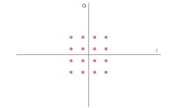
As shown above, the constellation points are typically arranged in a square grid with equal horizontal and vertical spacing.
Although data is binary the most common forms of QAM, although not all, are where there constellation can form a square with the number of points equal to a power of 2 i.e. 4, 16, 64 . . . . , i.e. 16QAM, 64QAM, etc.
By using higher order modulation formats, i.e. more points on the constellation, it is possible to transmit more bits per symbol. However the points are closer together and they are therefore more susceptible to noise and data errors.
The advantage of moving to the higher order formats is that there are more points within the constellation and therefore it is possible to transmit more bits per symbol.
The downside is that the constellation points are closer together and therefore the link is more susceptible to noise. As a result, higher order versions of QAM are only used when there is a sufficiently high signal to noise ratio.
To provide an example of how QAM operates, the constellation diagram below shows the values associated with the different states for a 16QAM signal. From this it can be seen that a continuous bit stream may be grouped into fours and represented as a sequence.

Normally the lowest order QAM encountered is 16QAM. The reason for this being the lowest order normally encountered is that 2QAM is the same as binary phase-shift keying, BPSK, and 4QAM is the same as quadrature phase-shift keying, QPSK.
Additionally 8QAM is not widely used. This is because error-rate performance of 8QAM is almost the same as that of 16QAM - it is only about 0.5 dB better and the data rate is only three-quarters that of 16QAM. This arises from the rectangular, rather than square shape of the constellation.
QAM advantages and disadvantages
Although QAM appears to increase the efficiency of transmission for radio communications systems by utilising both amplitude and phase variations, it has a number of drawbacks.
The first is that it is more susceptible to noise because the states are closer together so that a lower level of noise is needed to move the signal to a different decision point.
Receivers for use with phase or frequency modulation are both able to use limiting amplifiers that are able to remove any amplitude noise and thereby improve the noise reliance. This is not the case with QAM.
The second limitation is also associated with the amplitude component of the signal. When a phase or frequency modulated signal is amplified in a radio transmitter, there is no need to use linear amplifiers, whereas when using QAM that contains an amplitude component, linearity must be maintained.
Unfortunately linear amplifiers are less efficient and consume more power, and this makes them less attractive for mobile applications.
QAM vs PSK & other modes
When deciding on a form of modulation it is worth comparing AM vs PSK and other modes looking at what they each have to offer.
As there are advantages and disadvantages of using QAM it is necessary to compare QAM with other modes before making a decision about the optimum mode. Some radio communications systems dynamically change the modulation scheme dependent upon the link conditions and requirements - signal level, noise, data rate required, etc.
The table below compares various forms of modulation:
| Summary of types of modulation with data capacities |
||||
|---|---|---|---|---|
| Modulation | Bits per symbol | -- Error margin -- | Complexity | |
| OOK | 1 | 1/2 | 0.5 | Low |
| BPSK | 1 | 1 | 1 | Medium |
| QPSK | 2 | 1 / √2 | 0.71 | Medium |
| 16 QAM | 4 | √2 / 6 | 0.23 | High |
| 64QAM | 6 | √2 / 14 | 0.1 | High |
Typically it is found that if data rates above those that can be achieved using 8-PSK are required, it is more usual to use quadrature amplitude modulation. This is because it has a greater distance between adjacent points in the I - Q plane and this improves its noise immunity. As a result it can achieve the same data rate at a lower signal level.
However the points no longer the same amplitude. This means that the demodulator must detect both phase and amplitude. Also the fact that the amplitude varies means that a linear amplifier si required to amplify the signal.
More Essential Radio Topics:
Radio Signals
Modulation types & techniques
Amplitude modulation
Frequency modulation
OFDM
RF mixing
Phase locked loops
Frequency synthesizers
Passive intermodulation
RF attenuators
RF filters
RF circulator
Radio receiver types
Superhet radio
Receiver selectivity
Receiver sensitivity
Receiver strong signal handling
Receiver dynamic range
Return to Radio topics menu . . .

