
RF Attenuators: basics, types, symbols
RF attenuators have a surprising number of uses: reducing high power signals for test equipment, level control; impedance matching, and a number of other RF circuit design areas.
RF Attenuators Includes:
Attenuator basics
Attenuator specs
Resistive attenuator design
Attenuator resistor values table
Balanced resistive attenuator pads
Variable PIN diode attenuator
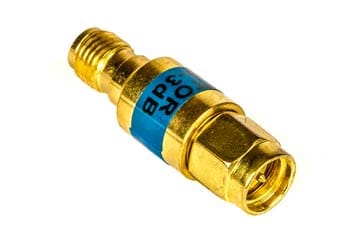
SMA attenuator
RF attenuators can be used for a variety of different purposes within many RF circuit designs and systems. These RF attenuators can be fixed, switched or even continuously variable.
Attenuators can also use a variety of different RF circuit design techniques: some used fixed resistors for fixed values of attenuators, others are switched, and other types may be variable using semiconductor technology to achieve this.
Whatever the technology and RF design techniques that are used, all attenuators serve to reduce the level of a signal, and surprisingly this can have many advantages in different situations.
What is an attenuator?
As the name implies RF attenuators reduce the level of the signal, i.e. they attenuate the signal. Typically the attenuation is defined in decibels, and fixed attenuators may be available in a variety of levels.
This attenuation may be required to protect a circuit stage from receiving a signal level that is too high. Also an attenuator may be used to provide an accurate impedance match as most fixed attenuators offer a well-defined impedance, or attenuators may be used in a variety of areas where signal levels need to be controlled.
There are many uses for these RF attenuators and although they may not always seem obvious initially, they are widely used in RF circuit design applications and RF systems of different types.
In some instances, RF attenuators may be required to reduce high levels of power and as a result they may need to incorporate a heatsink to ensure that the power can be suitably dissipated. It will be seen that some higher power RF attenuators incorporate a heatsink for this purpose.
Types of RF attenuator
Attenuators can be categorised in a number of ways according to their capabilities and the technologies they use:
Fixed RF attenuator: As the name implies fixed attenuators have a specific value and this cannot be changed. They may come in a variety of formats from small in-line items in a similar format to connector adaptors to those in small boxes with connectors on the ends to those incorporated within equipment.
Fixed attenuators may even be be incorporated into the RF circuit design itself, possibly set out on the printed circuit board design. These fixed RF attenuators are easy to design and are seen in many circuit designs.
- Switched RF attenuators: Switched RF attenuators are often used in test systems where levels may need to be changed. They are often seen as small boxes with a number of switches, typically with switches for 1, 2, 4, 8, etc dB changes. The levels often correspond to values of 2n and this accommodates continuous switching with just on and off switching of the different elements of the attenuator.
Switched attenuators may also be found in items of test equipment to change the levels, for example of a signal generator output. Manually controlled RF attenuators will use ordinary manually controlled switched, but those that need to be controlled electronically can use reed relays, although PIN diodes can often be used.
There are two main types of switched RF attenuator:
Switched section RF attenuator: As the name of this type of RF circuit design for an attenuator indicates, there are several sections, and different sections can be switched in or out of circuit to give the required level of attenuation.
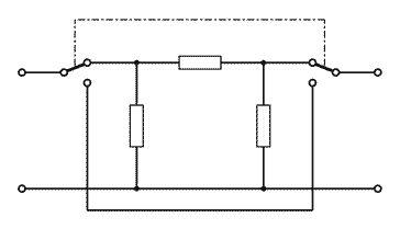
Switched section RF attenuator There will always be some leakage across the switches, and for higher value attenuators, this can provide an inaccuracy. As a rule of thumb it is found that if the combined isolation of the switches isolation is 20 dB greater than the desired attenuation, the leakage through the isolated shorting path path will change the attenuation by no more than 1 dB.
Switched element RF attenuators: For this form of switched attenuator, the individual resistors need to be varied to provide the different levels of attenuation.
It is theoretically possible to use standard switches for this type of attenuator, but in view of the fact that three switches are needed, FETs are typically used and it is this approach that is often adopted for RF attenuators used within MMIC or RFIC formats.

Switched element RF attenuator
Variable RF attenuators: Variable RF attenuators are normally used in applications where it is necessary to continuously vary the level of a signal. Typically variable attenuators provide a continuous level change by varying an analogue voltage on the input control line. These variable attenuators typically use soem form of voltage control that acts on a variable element like a PIN diode that works with other electronic components to provide a continuously variable level of attenuation.
Continuously variable RF attenuators are normally used where accuracy is not a prime requirement, and where an analogue voltage is available. They may be used in RF circuit design elements such as in feedback loops for controlling a level, or other similar applications.
Each different type of RF attenuator is used in different circuit applications, and can provide the required performance. In fact the level of performance that can be achieved can be exceedingly high.The different types of RF attenuator can be designed using different types of electronic component. Normally the type of RF attenuator dictates the type of components used.
Resistor RF attenuators: Resistor attenuators are used to provide fixed levels of attenuation. Fixed resistors are used and using these it is possible to provide accurate levels of attenuation, although the types of resistor used must not be inductive and the circuit layout must ensure that signal does not leak across each element.
If the levels need to be varied, this can be achieved by switching in different attenuator sections to provide the levels that are required. Also when large levels of attenuation are needed, it s often best to achieve this using more than one section
- PIN diode RF attenuators: PIN diode attenuators are used in attenuator designs where a continuously variable level is required.
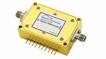
Typical PIN diode switched / programmable RF attenuator They are also widely used within switched attenuators where the PIN diodes enable the different elements to be switched in or out of circuit.
- FET RF attenuators: FET attenuators can be used in attenuator designs where a continuously variable level is required. Like a PIN diode attenuator, FET attenuators can use an analogue control voltage to control the level of attenuation. They can also be used to switch different electronic component values into circuit to achieve the required level of attenuation.
These are only broad categories for RF attenuators - they can be categories in a variety of ways according to the application and the type of attenuator technology that is used.
RF attenuator symbol
It is often necessary to show the block symbol in a circuits schematic diagram for an attenuator without necessarily showing all the individual components.
There is an attenuator symbol that has been widely adopted.

For some applications a variable attenuator symbol may be required:

RF attenuator applications
RF attenuators are used in a wide variety of applications in RF circuits. They are a key building block used in many areas of RF design:
- Reduce signal level: The basic concept behind an attenuator is to reduce the signal level. This can be required to control levels within a circuit to keep them within the required range. One particular use is for testing high power RF signals, e.g. in transmitters where the signal level needs to be reduced before it can be applied to an item of test equipment.
- Improve impedance match: By its very nature an impedance matched RF attenuator will improve the impedance match. This can be very useful when driving RF mixers that are match sensitive and their performance will be degraded if a poor match is seen.
- Variable level control: RF attenuators can be used for level control on the output of items such as signal generators. It is far better to be able to generate an accurate fixed level from the basic generator and then used switch attenuators to reduce the signal to the required level.
RF attenuators are used widely within RF circuit designs for a variety of reasons. Fortunately these attenuators are easy to design and using surface mount technology where the stray inductance levels are very low, their performance can be exceedingly good.
RF attenuator specifications
When selecting an RF attenuator for use in an RF design, system of other use, it is good to have a good understanding of all the specifications. Whilst the basic attenuation specification is important, there are various other parameters that need to be considered.
Aspects like the attenuation accuracy, step range, attention range, temperature stability and many more all need to be considered..
Design of fixed RF attenuator
The RF circuit design for the fixed formats attenuator are relatively straightforward using only simple calculations to arrive at the final values.
There are two main formats for RF attenuators, namely "Π" and "T" formats. The Π format has resistors to ground from the input and output connection and a series resistor between them.
The "T" section attenuator has two inline resistors, one at the input and the other at the output with a single resistor to ground at the junction of the two series resistors.
The calculations for the resistors depend upon the format of the actual attenuator pad.
RF attenuators are needed in many areas of RF circuit design providing the ability to control the level of a signal at a given point in a circuit or system. They are used in many areas of circuit design, it RF systems and also to ensure that power is limited so that it does not overload or destroy other circuits.
More Essential Radio Topics:
Radio Signals
Modulation types & techniques
Amplitude modulation
Frequency modulation
OFDM
RF mixing
Phase locked loops
Frequency synthesizers
Passive intermodulation
RF attenuators
RF filters
RF circulator
Radio receiver types
Superhet radio
Receiver selectivity
Receiver sensitivity
Receiver strong signal handling
Receiver dynamic range
Return to Radio topics menu . . .

