Demodulation is a key process in the reception of any amplitude modulated signals whether used for broadcast or two way radio communication systems.
Demodulation is the process by which the original information bearing signal, i.e. the modulation is extracted from the incoming overall received signal.
The process of demodulation for signals using amplitude modulation can be achieved in a number of different techniques, each of which has its own advantage.
The demodulator is the circuit, or for a software defined radio, the software that is used to recover the information content from the overall incoming modulated signal.
AM demodulators are found in many items of radio equipment: broadcast receivers, professional radio communication equipment, walkie talkies - AM is still used for air-band radio communications.
Detection or demodulation
The terms detection and demodulation are often used when referring to the overall demodulation process. Essentially the terms describe the same process, and the same circuits.
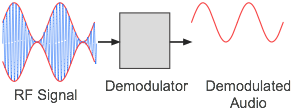
As the name indicates the demodulation process is the opposite of modulation, where a signal such as an audio signal is applied to a carrier.
In the demodulation process the audio or other signal carried by amplitude variations on the carrier is extracted from the overall signal to appear at the output.
As the most common use for amplitude modulation is for audio applications, the most common output is the audio. This may be broadcast entertainment for broadcast reception, and for two way radio communications, it is often used for land communications for aeronautical associated applications - often within walkie talkies. AM amplitude modulation demodulation principle
Terms like diode detector, synchronous detector and product detector are widely used. But the term demodulation tends to be used more widely when referring to the process of extracting the modulation from the signal.
The term detection is the older term dating back to the early days of radio. The term demodulation is probably more accurate in that it refers to the process of demodulation, i.e. extracting the modulation from the signal.
AM demodulation techniques
There are a number of techniques that can be used to demodulate AM signals. Different types are used in different applications to suit their performance and cost.
Diode rectifier envelope detector: This form of detector is the simplest form, only requiring a single diode and a couple of other low cost components. The performance is adequate for low cost AM broadcast radios, but it does not meet the standards of other forms of demodulation. Circuit of an envelope detector as used in an AM radio receiver.
It has a high level of distortion, and performs badly under conditions of selective fading such as those experienced on the medium and short wave bands.
That said the diode detector has been in use for many years. It was widely used for domestic and professional valve or tube radios, and when semiconductors replaced valves, simple diode detectors were very easy to implement. For more modern radios using integrated circuits, other forms of AM detector or AM demodulator are easier to implement.
Product detector: It is possible to demodulate amplitude modulated signals with a receiver that incorporates a product detector of mixer and a local beat frequency oscillator or carrier injection oscillator. In its basic form, the local oscillator is not synchronised to the incoming signal carrier.
Normally a product detector is used for the reception of single sideband - a derivative of AM. To demodulate SSB, a circuit known as a product detector is used. Single sideband is a form of amplitude modulation where the carrier and one sideband is removed leaving only one sideband.
To reconstitute the signal, an oscillator known as a beat frequency oscillator or carrier insertion oscillator is used to replace the carrier of the AM that has been removed and the combination is mixed in a mixer - this produces the product of the two signals, which results in the original modulating signal being produced.
The circuit can also be used for listening to Morse code signals. Here is is used to produce a beat between the intermittent carrier so that the Morse code can be heard.
For demodulating AM, the the receiver is tuned so that there is a zero beat between the carrier of the AM and beat frequency oscillator. The demodulated audio then appears at the output of the product detector. For this system to operate correctly, the receiver must maintain its frequency such that the BFO frequency is exactly the same as that of the incoming carrier otherwise an annoying beat note will be continually heard.
Synchronous detection: The synchronous detector or demodulator is effectively a development of the product detector circuit and it therefore provides the optimum performance for the demodulation of AM signals. It uses many more components than a simple diode detector, but in view of the uptake of integrated circuit technology, it is very easy to incorporate this form of demodulator into many radio receivers for almost zero incremental cost.
The synchronous AM demodulator uses a mixer or product detector with a local oscillator signal. The local oscillator signal is synchronised to the incoming signal carrier so that it produces no beat note with the incoming carrier. The sidebands of the AM signal are then demodulated to provide the required audio signal.
In view of its much superior performance and the ease of incorporating it into ICs, this form of demodulator is used in many AM broadcast receivers as well as professional AM based radio communications equipment and walkie talkies, etc.
These three forms of circuit are the most commonly used methods and circuits for demodulating amplitude modulated, AM signals.
AM demodulators are used within any piece of radio equipment that is used for AM broadcast reception or radio communications systems that use amplitude modulation. Although amplitude modulation is not as widely used as it was many years ago, it is still used for broadcasting on the Long, Medium and Short Wave bands.
Possibly its greatest use for professional radio communications is for aeronautical radio communications. Here it is widely used for ground communications and walkie talkies are widely used. each of these different forms of radio communication will require for their to be an AM demodulator.