
Power Supply Specifications, Specs
When selecting a power supply, either linear power supply or switch mode power supply, it is necessary to understand the various specifications to choose the right one.
Power Supply Circuits Primer & Tutorial Includes:
Power supply circuits overview
Linear power supply
Switch mode power supply
Capacitor smoothing
AC rectifier circuits
Voltage regulator circuits
Zener voltage regulator circuit
Over-voltage protection
PSU specs
Digital Power
Power management bus: PMbus
Uninterruptible power supply
When choosing and buying a power supply it is necessary to be able to understand the specifications given in the data sheet so that a power supply with the right performance can be selected.
There are several specifications used to detail the performance of the power supplies. Each one details a different aspect of the performance of a power supply, and dependent upon the application, some will be more important than others.
Power supplies can be either linear, using a linear voltage regulator, or switch mode power supplies. Both types are widely used, but often in they are used different applications as a result of their different characteristics.
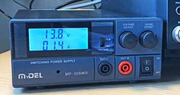
Voltage and current specifications
The primary power supply specifications are the voltage and current output parameters. In terms of the voltage, the power supply may be fixed or it may have a variable output. It is necessary to check whether the power supply has a fixed or variable output.
If the power supply has a fixed output there will be a small adjustment that can be made and it may be necessary to check that it can be adjusted to the required value if the voltage required is not exactly that quoted on the specification sheet. If the power supply has a variable range then it is necessary to ensure that it covers the required range.
In terms of the current it is necessary to ensure that the power supply will be able to provide the required level of current and have a degree of margin beyond that minimum requirement.
When calculating the requirement for the power supply specification for current it is necessary to take account of what is termed the inrush current. This in-rush current occurs when an item is turned on and a large surge of current is drawn to charge up capacitors, etc. This inrush current can be several times the ordinary operating current.
Line regulation
Power supply specifications detail figures for a parameter entitled "line regulation." It is found that when the line or input voltage changes then a small variation may be seen on the output. The line regulation figure details this change.
It is important to ensure that if the voltage of the output is critical, then the line regulation is such that is does not fall outside the required output voltage limits with the expected line variations.
It is also necessary to add this to any other power supply output voltage variations like the load regulation and time and temperature stability.
The line regulation specification is normally quoted in millivolts for a given input variation. It may also be expressed or as a percentage of the output voltage and it should typically be a few millivolts (e.g. 5 mV) or around 0.01% of the maximum output voltage for most power supplies for a change of line voltage anywhere within the operating range.
Load regulation
Another important power supply specification is called the "load regulation." It is found that when a load is added to the output of a power supply the voltage at the terminals can fall slightly. This is obviously not desirable because the output voltage should remain exactly constant in an ideal world.
The power supply load variation is normally quoted as a in millivolts variation or as percentage of the maximum output voltage It might typically be a few millivolts (e.g. 5 mV) or 0.01% for a step load change from 0 to 100% load. It is normally quoted for a constant line voltage and at steady temperature.
It may also be found that there could be a noticeable voltage drop along the wires from the power supply to the load. This can obviously be reduced by using thicker wires that will have a lower resistance. However some power supplies have additional terminals for remote sensing.

Using remote sensing, the power supply is connected to the load in the normal way, but additional wires are used to sense the voltage actually on the load.
The sense wires carry virtually no current, and apart from being much thinner, they will have virtually no voltage drop along them. They will sense the voltage at the load, and feed this information back to the power supply so that the voltage regulator circuitry regulates to the voltage on the load and not that at the output of the power supply.
Ripple and noise
The ripple and noise parameters are another important power supply specification. It is possible that noise and other impulses on the power line can be transferred to the output of the circuit that is being powered. In order to minimise this, especially for sensitive circuits it is necessary to ensure that the power lines are as clean as possible.
The ripple and noise on the output is combined as a single specification. For linear supplies, ripple frequency is normally be at twice the line frequency. For switching supplies ripple and spikes will arise from the switching action of the supply.
The ripple components are often given as RMS figures, but for switching supplies a peak-to-peak measurement is more useful because it shows the extent of the spikes arising from the switching.
Most good supplies should offer noise and ripple figures of better than 10 mV RMS and for switching supplies figures of 50mV or less should be achievable in many cases, although very high current supplies may have slightly higher values.
Temperature stability
Temperature is one of the main causes for circuit conditions changing, and in the case of power supplies, both linear power supplies and switch mode power supplies, it can cause changes in the output voltage.
Voltage references (Zener diodes, etc) can be one of the main causes of voltage change, but other electronic components change as well - resistors being the main one after the reference diode.
Often various forms of temperature compensation can be added during the electronic circuit design stage of the power supply, and this will considerably reduce any drift, but there will always be some.
Even small changes can affect some circuits, so in these cases, it is important to check the power supply temperature stability figures.
Figures for the power supply temperature stability will be given in the data-sheet. The parameter is measured as a percentage or absolute voltage change per degree C. Typically, this might be in the region of 0.02% / °C or 2 mV / °C. Naturally these figures are only a guide to what some supplies state.
Stability with time
All components change their values slightly over time, so it is not surprising to find that power supplies, but linear regulator types and switch mode power supplies, both vary by a small amount with time.
Although the amounts of change are normally small, they may be important in some applications. As a result figures for the voltage output stability with time are often quoted within the overall power supply specifications.
For the stability specification, the output voltage of the power supply will be measured over a period of time under constant load and input voltage and the voltage drift measured. Typically, this will be a few millivolts (e.g. five to ten) over a period of ten hours.
Power supply current limiting and over-voltage
It is always wise to ensure that any power supply, whether a linear voltage regulator, or a switch mode power supply has various forms of protection incorporated to prevent damage in case of a failure of some form.
There are two main forms of protection that can be found in linear and switch mode power supplies:
Short circuit protection: Short circuit protection is needed in case the equipment being powered develops a short circuit or starts to take current beyond its design current. By having short circuit protection in the power supply, this limits the current to a maximum level.
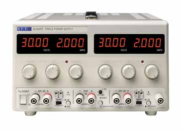
Many bench or laboratory power supplies have an adjustable limit, and this can be useful because it means that the limit can be adjusted for the requirements of the circuit being powered.
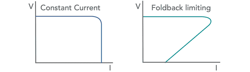
There are also two forms of current limiting. The first is called constant current limiting. This limits the current to a maximum level and it remains at this level if there is an overload. Another form of current limiting in the power supply, is called fold-back current limiting. This reduces the current from the maximum progressively as the overload increases. In other words the current folds back.
Over-voltage protection: It is possible that the series element, especially in a linear voltage regulator may fail. In this case the full pre-regulated voltage could appear at the output and could possibly damage the circuits being powered. Over-voltage will cut the power supply out as an over-voltage condition occurs and prevent the full over-voltage condition occurring.
It is always worth checking the power supply specification to ensure that over-current or short circuit protection as well as over-voltage protection are present, as considerable damage could occur in the event of either occurrence.
Power supply specifications
Although the power supply specifications mentioned above are generally the most widely used, others may also appear, and these may be important for some more specialised applications. In general it is possible to interpret them, at least in general terms, and gain a good idea of the required operation of the power supply.
More Circuits & Circuit Design:
Op Amp basics
Op Amp circuits
Power supply circuits
Transistor design
Transistor Darlington
Transistor circuits
FET circuits
Circuit symbols
Return to Circuit Design menu . . .

