Understanding Power Supply Circuits
The electronic circuits used within power supplies are designed to provide the highest performance with the maximum power efficiency - understand more about the circuits & techniques.
Power Supply Circuits Primer & Tutorial Includes:
Power supply circuits overview
Linear power supply
Switch mode power supply
Capacitor smoothing
AC rectifier circuits
Voltage regulator circuits
Zener voltage regulator circuit
Over-voltage protection
PSU specs
Digital Power
Power management bus: PMbus
Uninterruptible power supply
Power supplies are an important element in many items of electronic equipment where they provide the power at the right voltages and with the required levels of current, taking an input from an overall power source.
While some are battery driven, others need mains power supplies, and the power supply circuits and their electronic circuit design is of paramount importance to the successful operation of the whole equipment.
Power supply electronics can take many forms from linear power supplies to switch mode power supplies and buck regulators to boost power supplies, and more, and each have their own types of electronic circuit design topologies.
Although there is so much variation in the types of power supply and their electronics, techniques and the circuits, the electronic circuit designs for these units can be split into a number of sections or building blocks.
These circuits will vary somewhat from one power supply to another, but splitting the power supply electronics down into blocks helps understand what is going on and how they work.
However it should be remembered that not all supplies will have exactly the same block diagrams in view of the variation in their operation.
Some may not have all the circuit blocks, dependent upon their operation - some, for example, may just have a voltage regulator, or they may be used for voltage conversion from one level to another within a circuit.
Each circuit block is important to the operation of the power supply as a whole, but each section of the power supply electronics is required to perform its function satisfactorily for the successful operation of the whole electronic unit.
WARNING!: Many power supplies will contain mains or power line voltages which are hazardous. Extreme care must be taken when dealing with these circuits, as electric shocks could be fatal. Only qualified personnel should deal with the internal circuitry of power supply electronics circuits.
Types of electronics power supply circuit
Power supplies can take many forms dependent upon the applications for which they are intended. There is a huge variety of different types and circuits available.
There are a number of technologies that can be used, each with its own advantages and disadvantages and as a result it is possible to select the type required dependent upon the electronic circuit conditions and the overall requirements.
There are three major types or technologies for power supply circuits:
Rectified and smoothed power supply: These electronics power supplies are the simplest types, and are generally used for non-critical applications where performance is not a major issue.
This type of power supply was widely used in thermionic valve or vacuum tube equipment as it was not so easy to regulate supplies, and often the requirements were not so critical.
Linear regulated power supply: This form of electronics power supply is able to provide a very high level of performance. However the fact that it uses a series regulator element means that it can be comparatively inefficient, dissipating a significant proportion of the input power as heat.
As a result of their high levels of dissipated heat, inefficiency, and the added cost these power supplies are being used les, although they are used in many areas where very clean supplies are needed.
Read more about . . . . Linear Power Supplies.
Switch mode power supply: In this form of power supply, electronics circuits use switching technology to regulate the output. Although spikes are present on the output, the performance of these power supply circuits has improved significantly in recent years.
They offer very high levels of efficiency and in view of this they can be contained in much smaller packages than their linear equivalents. Their high levels of efficiency mean that less heat is dissipated and this reduces the cost of heat removal which affects the cost of the power supply itself as well as that of the overall equipment.
Read more about . . . . Switch Mode Power Supplies, SMPS.
The different types of power supply are each used for different types of application according to their advantages.
It is even possible that a variety of power supply circuits, technologies, and techniques may all be used within the same piece of electronic equipment.
Major power supply electronics blocks
A power supply can be split into a number of elements, each providing a function within the overall power supply. Naturally these areas can be rather arbitrary, and may vary slightly dependent upon the actual power supply design, but they can be sued as a rough overall guide.
Power input filtering: It some instances it is necessary to ensure that spikes from the power line do not enter the power supply, and that noise that might be generated by the power supply does not enter the power lines. To achieve this circuitry to remove noise and limit the effects of incoming spikes is placed at the input to the power supply.
In many cases any filtering at this point is quite minimal, although with the increased need for high levels of electromagnetic compatibility, EMC, many more power supplies are incorporating filtering and other elements of EMC good practice to ensure that interference does not affect them, nor do they spread unwanted or spurious emissions back along the input power line.
Often series inductors with capacitors to ground are used to give a good level of filtering, and and this should be combined with ensuring that the earth connections are well managed.
In addition to this screening is likely to be required to prevent issues with radiated interference. This can be needed, especially with switch mode supplies which generate quite high levels of fast spikes.
Input transformer: If a power supply using mains / line supplies of 110 or 240 volts AC is used, then the input usually has a transformer to transform the incoming line voltage to required level for the power supply design.

The transformers are generally large and relatively costly as they are wound components and their manufacture tends to require complicated mechanical machines.
Rectifier: It is necessary to change the incoming AC waveform to a DC waveform. This is achieved using an AC rectifier circuit. Two types of rectifier circuit may be used - full wave and half wave rectifiers. These effectively block the part of the waveform in one sense and allow through the part of the waveform in the other sense.

The rectifying action of a diode There are several types of circuit for rectifiers, namely half wave, full wave and full wave bridge rectifier circuits
Half wave rectifier circuit: The half wave rectifier circuit is the simplest using a single diode. It acts by preventing the current flow in one direction and as a result only one haf of the cycle is used making it rather inefficient.

Half wave rectifier with transformer input The other issue with the half wave rectifier circuit is that smoothing the output is more difficult because there is longer between the peaks than if a full wave rectifier had been used. This means poorer ripple performance from the overall power supply circuit, and the need for larger and more costly capacitors to achieve an acceptable level of performance.
Full wave rectifier circuit: The advantage of the full wave rectifier circuit configurations is that they utilise both halves of the incoming AC waveform. This is not only more efficient, but it also enables better smoothing to be achieved with smaller capacitors. Where possible, full wave rectifiers are to be preferred in view of their performance.

Comparison between the half wave and full wave rectifier operation The most straightforward form of full wave rectifier uses two diodes, but requires a split transformer in the circuit shown below.

Full wave rectifier circuit using two diodes and a centre tapped transformer While this circuit does enable full wave rectification to be achieved in power supplies, it does require the use of a centre tapped transformers. As both windings are required to provide the full voltage this does make them more expensive.
Full wave bridge rectifier circuit: The full wave bridge rectifier is used in many power supply circuits. It has the advantage of providing full wave rectification, but without the need for a centre tapped transformer.
The slight downside is that it does require the use of four diodes, but as these are not costly items, this is not normally an issue. The other issue is that for each half of the waveform, it experiences two diode voltage drops, and this may be an issue for some power supply circuit designs.
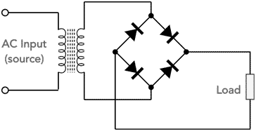
Full wave rectifier using a bridge rectifier circuit Often the four diodes used for the bridge rectifier can be obtained in a single bridge rectifier package. These provide an attractive way of containing the diodes, and for manufacturers it means that only one part needs to be used in the assembly rather than four. Also where the heat is sufficient to require a heatsink, the bridge rectifier can be obtained with a heat sink mountable package, and again, only one electronic component needs to be fixed.
Note on Diode Rectifier Circuits:
Diode rectifier circuits are used in many areas from mains power supplies to radio frequency demodulation. The diode rectifier circuits use the capability of the diode to only pass current in one direction. There are several varieties from half wave to full wave, bridge rectifiers, peak detectors and more.
Read more about Diode Rectifier Circuits
Rectifier smoothing: The output from the AC rectifier circuit consists of a waveform varying from zero volts to 1.414 times the RMS input voltage (less any losses introduced by the rectifier).
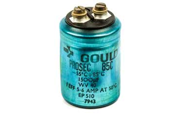
In order that this can be used by electronics circuits, it needs to be smoothed. This is achieved using a capacitor. It will charge up over part of the cycle and then as the voltage falls it will supply the current to the circuit, charging up again as the voltage rises.
The waveform to be smoothed will depend upon the type of rectification used wether it is full or half wave. The differences between the half and full wave rectification can be seen, with the ful wave rectifier circuit in the power supply providing a lower level of ripple.

Full wave rectifier enables better smoothing Read more about . . . . Capacitor Smoothing Circuits.
- Regulation: Even after the rectified voltage has been smoothed, there may still be significant levels of residual hum. Also the voltage will vary as different levels of current are drawn.
To provide a stable voltage output from the power supply with little residual hum and noise a voltage regulator circuit is required. Regulators are able to provide a stable voltage at a set or variable level dependent upon the requirement.
Voltage regulator circuits can take a variety of forms, generally using either linear or switching mode circuit techniques to bring the output voltage to the required level.
Linear power supplies: The linear power supply circuit is the more traditional form of power supply electronics. It uses a series or shunt element to ensure that the voltage at the output remains stable. While these supplies produce very clean outputs in terms of their regulation, they are not at all efficient - a factor that is increasingly important these days.
Read more about . . . . Linear power supply circuits.
Switch mode power supplies: Switch mode power supplies use a technique where the regulator element is turned on and off to provide charge to the output where the charge passed to it is stored. Sufficient charge is supplied to the output by switching the regulator element on and off so that the output voltage remains constant.
Switch mode regulators circuits are far more efficient than linear ones although the output may not be as clean, although modern SMPSs provide exceedingly good levels of output regulation these days. However they are far more efficient than linear power supplies, often offering efficiency levels well over 90%, and many offering over 95%.
With switch mode regulators it is possible to either reduce the voltage using what is called a step down or buck converter, or a step up or boost converter. These switch mode circuit modules can also be bought on their own as modules to efficiently increase of reduce voltage levels within a circuit.
Read more about . . . . Switch mode power supply regulation.
Over voltage protection: Over-voltage protection is very important for many power supplies. In the event of the failure of the regulator it is possible under some circumstances that the output voltage from the power supply could rise to a level that could damage the circuitry being powered.
To prevent this occurrence over-voltage protection circuitry can be used. This circuit element detects the level of the output voltage and if it starts to rise above its acceptable limits it will trip, removing the supply from the regulator and usually clamping the output from the regulator to zero volts, thereby protecting the remaining circuitry from damage.
Read more about . . . . Over-voltage protection circuits & electronics.
Not all of these power supply electronics building blocks are used in every power supply. Most will have a transformer, smoothing and a regulator, but the other elements may or may not be included dependent upon the specification.
Power supply specifications
When buying or selecting a power supply it is necessary to check the specifications and understand what they mean. Everything from the voltage and current ratings, to ripply, load regulation, input voltage regulation and the like.
By understanding the specifications for the different power supplies and how the various levels will affect the circuits being powered, then it is possible to select the right power supply for the required electronic circuit or unit.
Power supply circuits, regulated using a linear or switch mode regulator are widely used. The switching regulator approach is used most widely, especially in computers, and very many other items of electronic equipment - in fact switch mode power supplies are by far the most popular now because of their efficiency, lower cost and smaller size. Many ICs are available for the function and they are light, efficient and very cost effective.
More Circuits & Circuit Design:
Op Amp basics
Op Amp circuits
Power supply circuits
Transistor design
Transistor Darlington
Transistor circuits
FET circuits
Circuit symbols
Return to Circuit Design menu . . .