
FET Datasheet Specifications & Parameters
Many different parameters and specifications appear in FET datasheets - everything from the Vgs to RDSON.
FETs, Field Effect Transistors Includes:
FET basics
FET specifications
JFET
MOSFET
Dual gate MOSFET
Power MOSFET
MESFET / GaAs FET
HEMT & PHEMT
FinFET technology
IGBT
Silicon carbide, SiC MOSFET
GaN FET / HEMT
FET data-sheets like those for other forms of electronic component contain a host of different parameters and specifications which define the performance of the particular device.
For electronic circuit design or when replacing an existing FET it is important to understand the different parameters and specifications that appear in the data-sheets so that the correct semiconductor device can be chosen and used.
Different parameters may be of greater or lesser importance dependent upon the actual electronic design being undertaken. For RF designs, for example RF aspects like capacitance high frequency performance and the like will be important, but for power supplies, heat dissipation and current capacity may be key.
However a good understanding of all the main FET parameters is useful so that a the whole performance can be assessed to ensure its suitability for any given general electronic circuit design or RF design.
Understanding the different FET parameters will enable the right FET to be chosen for a particular electronic design, an RF design, or for replacement, especially if the exact replacement is not available.
Major FET data-sheet specifications & parameters
At one time it was possible to obtain printed data-sheets or even books of data-sheets when undertaking an electronic design. These days the data-sheets for electronic components are normally available online. Interestingly, though the format for the data-sheets has remained the same - the only real change has been the method of delivery.
It is quite normal when starting an electronic circuit design, to search the Internet for suitable devices. This makes it much quicker than having to wait for a data-sheet to be sent though if one was not available in the electronics design laboratory.
The main FET specifications used in data-sheets are summarised in the list below. Some of the parameters are particularly important for different types of FET, e.g. JFET while others may be more applicable to MOSFETs, or other forms of field effect transistors.
• Type of FET
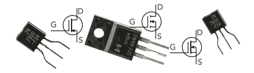
One of the key parameters for any electronic design will be the type of FET. Whether it is a JFET, MOSFET, dual gate MOSFET, power FET, IGBT or whatever, this will be the first parameter to be assessed.
The different types of FET tend to be used in different scenarios or electronic designs:
JFET: JFETs use a reverse biassed diode on the gate input to provide the control input for the semiconductor device. They are easily produced and they are often used as low cost general purpose designs. One particular example might be the 2N3819 which is a solid workhorse that has been available for many years.
MOSFET: The MOSFET has an insulated gate and therefore it has a very high input impedance. These FETs are also widely available and can be used in a very wide variety of electronic designs.
Dual gate MOSFET: This form of MOSFET has two gates. The second gate enables it to be used in RF designs such as RF mixers where one gate is used for the incoming signal and the other for the local oscillator. The second gate also enables the feedback capacitance from the output circuit to the input to be reduced to prevent spurious oscillation. As a result, these devices are also used for RF amplifiers for VHF and above where even small values of capacitance are significant.
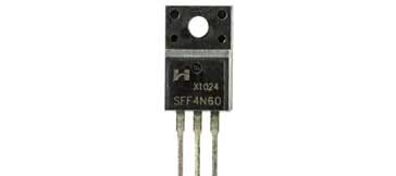
Power MOSFET : Many FETs are used for what may be referred to as "standard" applications or small signal circuit designs. However some FETs are used for power related electronic circuits: in power supplies - particularly switch mode power supplies and other power switching circuit designs where higher current and voltage levels are encounter. There are many power MOSFETs that are fabricated just for these circuits and scenarios and they are able to handle much higher current and voltage levels.
GaAs FET : GaAs FETs are a particular form of FET. Often they are used for low noise RF amplifiers and other RF designs for frequencies at VHF and above. They are a specialised form of junction FET which are useful for these circuit designs.
IGBT - insulated gate bipolar transistor: IGBTs are used for a number of switching circuits. They are a combination of a MOSFET with an insulated gate and a bipolar transistor. They are a form of unidirectional non-latching switch that can be used in many switching electronic circuits where they have some advantages over either a bipolar transistor or a power MOSFET.
SiC FETs: Silicon carbide is being used increasingly for a number of semiconductor devices these days. Silicon carbide provides much higher breakdown voltages as well as a much higher resilience to high temperature operation. As a result SiC FETs are ideal for use in a variety of power switching circuit designs. Their use can provide overall cost reductions and performance improvements in many circuits. Even though the cost of the device is higher, the improved efficiency and performance mean that other circuitry and thermal considerations can be reduced.
GaN FETs: Gallium nitride is another material that is being used for some power circuit designs, particularly where high frequencies are needed. Accordingly GaN FETs, which are a form of HEMT are being used in many microwave power circuits. Their use, although not cheap, provides some significant performance enhancements.
Even though a number of FET technologies have been mentioned here several other types can be selected. A review of the different technologies may be required to select the most suitable type of FET.
• Gate source voltage specification, VGS
The FET parameter VGS is the rating for the maximum voltage that can be tolerated between the gate and source terminals.
The purpose for including this parameter in the data sheet is to prevent damage of the gate oxide. The actual gate oxide withstand voltage is typically much higher than this but it varies as a result of the tolerances that exist in the manufacturing processes. It is advisable to remain well within this rating so that the reliability of the device is maintained. Often many design rules indicate that the device should only be run to 60 or 70% of this rating.
• Drain-source voltage specification, VDSS
This is a rating for the maximum drain-source voltage that can be applied without causing avalanche breakdown. The parameter is normally stated for the case where the gate is shorted to the source and for a temperature of 25°C. Depending on temperature, the avalanche breakdown voltage could actually be less than the VDSS rating.
When designing a circuit, it is always best to leave a significant margin between the maximum voltage to be experienced and the VDSS specification. Often they may be run at around 50% VDSS to ensure reliability.
• Gate reverse leakage current, Igss
This parameter is particularly relevant to junction FETs and is the leakage current from minority carriers across the reverse biassed gate-channel junction. Normally it is very small, especially as FETs are normally fabricated on silicon, although it can also be important for semiconductor devices such as GaAs FETs.
• Threshold voltage VGS(TH)
The threshold voltage VGS(TH) is the minimum gate voltage that can form a conducting channel between the source and the drain. It is normally quoted for a given source drain current.
• Drain current at zero gate voltage, Idss
This FET parameter is the maximum continuous current the device can carry with the device fully on. Normally it is specified for a particular temperature, typically 25°C.
This FET specification is based on the junction-to-case thermal resistance rating RθJC (junction / channel temperature) and the case temperature.
This FET parameter is of particular interest for power MOSFETs and when determining the maximum current parameter no switching losses are accounted for. Also holding the case at 25°C is not feasible in practice. As a result the actual switching current should be limited to less than half of the Idss at TC = 25°C rating in a hard switched application. Values of a third to a quarter are commonly used.
• Gate source cut-off voltage , VGS(off)
The gate source cut-off voltage is really a turn-off specification. It defines the threshold voltage for a given residual current, so the device is basically off but on the verge of turning on.
The threshold voltage has a negative temperature coefficient, i.e. it decreases with increasing temperature. This temperature coefficient also affects turn-on and turn-off delay times which has an impact on some circuits.
• Forward transconductance specification, Gfs
The forward transconductance, gfs of a FET is an important parameter and it is a measure of the sensitivity of drain current to changes in gate-source voltage. The forward transconductance, Gfs is normally quoted for a Vgs that gives a drain current of about half of the maximum current rating value and for a VDS that ensures operation in the constant current region of the semiconductor device.
It is interesting to note that the transconductance of a FET is influenced by gate width of the device and and it increases in proportion to the active area within the semiconductor device.
• Input capacitance, Ciss
The input capacitance parameter for a FET is the capacitance that is measured between the gate and source terminals with the drain shorted to the source for AC signals. In other words this is effectively the capacitance between the gate and channel. Ciss is made up of the gate to drain capacitance Cgd in parallel with the gate to source capacitance Cgs. This can be expressed as:
• Drain-source on resistance, Rds(on)
With the FET turned hard on, this is the resistance in ohms exhibited across the channel between the drain and source. It is particularly important in switching applications from logic to power switching as well as in RF switching, including applications in mixers. FETs typically are able to provide a good performance for switching and have a relatively low Rds(on) value.
• Power dissipation, Ptot
This FET specification details the maximum continuous power that the device can dissipate. The power dissipation is normally specified in free standing in air, or with the base held at a given temperature, typically 25°C.
The actual conditions, whether held in a heat-sink, or in free air will depend upon the device types and the manufacturer. Obviously power FETs are more likely to detailed in a condition where they are held on a heatsink, whilst the free air condition is applicable to signal FETs.
The ability of the power semiconductor devices to be heatsink mounted will be detailed in the mechanical specification.
Other points to consider
Although the data sheet parameters are very important, there are also several other aspects to the selection of electronics components, and in this case FETs, for a particular circuit design.
These additional points, look at several points outside the data-sheet. These points can be just as important as the data-sheet parameters in the choice of the right component.
By considering these points, the best FET can be chosen, not only in terms of the basic parameter specifications, but also in terms of other factors that are equally or even more important.
Key Aspects of Component Selection:
Although it is possible to make many decisions about selecting the right component for a circuit design from the datasheet parameters, this is not the only basis for selecting the right components as there are several other attributes not in the data-sheets that need to be embodied in any decision. These are equally important as the basic specification parameters, but not always taken into account. In our web page, we reveal the key additional aspects to consider so that the overall best choice is made.
Read more about secrets of selecting components.
FET datasheets contain a host of different parameters and specifications to define the performance of the FET. These are all set out in the various datasheets that will enable the correct choice of FET to be made.
The parameters and specifications contained within the datasheets are not the same as those used for bipolar technology and therefore it sometimes takes a little longer to take on board what the specifications actually mean for anyone not so familiar with FET semiconductor device technology.
More Electronic Components:
Batteries
Capacitors
Connectors
Diodes
FET
Inductors
Memory types
Phototransistor
Quartz crystals
Relays
Resistors
RF connectors
Switches
Surface mount technology
Thyristor
Transformers
Transistor
Unijunction
Valves / Tubes
Return to Components menu . . .

