
Power Supply Current Limiter Circuits
Current limiter techniques and circuits using diodes and transistors to provide a current limiter function for power supplies and other circuits.
Linear Power Supply Circuits Primer & Tutorial Includes:
Linear power supply
Shunt regulator
Series regulator
Current limiter
78** series regulators & circuits
LM317 voltage regulator & circuits
LDO, low dropout regulators
See also:
Power supply electronics overview
Switch mode power supply
Capacitor smoothing
Over-voltage protection
PSU specs
Digital Power
Power management bus: PMbus
Uninterruptible power supply
Current limiter circuits are key to power supplies, protecting them in cases of a short circuit or other overload condition.
In view of the possible damage to a power supply in cases of overload, current limiters are almost always fitted, and they are a standard feature incorporated into regulated power supply ICs.
As the name suggests, the current limiting circuit limits the current from the regulated power supply to a maximum amount determined by the circuit, and in this way, severe damage to the circuits, both the power supply and the circuit being powered can be avoided.
These circuits are more applicable to linear power supplies, although similar sensing techniques can be used in switch mode power supplies.
Types of current limiting
As with any technology and type of electronic circuit, there are a few options from which to choose and choices need to be made dependent upon the particular requirements for the electronic circuit design.
The same is true of the current limiters using within regulated power supplies where the current limiter circuits fall into particular categories.
There are two main types of current limiter circuit:
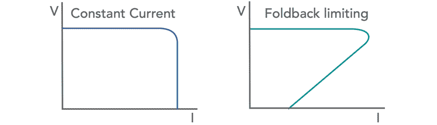
• Constant current limiting :
Using constant current limiting, the output voltage is maintained as the current rises until a point is reached where a maximum is reached. At this point the current maintained at this level whilst the voltage falls with increasing load.

This is the most basic form of current limiting used in regulated power supplies. The circuitry is simple and uses just a few electronic components but it does not reduce the current in the case of a short circuit - it is maintained at the maximum level and this could give rise to damage within the circuitry.
One of the disadvantages is that as the current limiting starts to operate, the maximum current is drawn, but at this point the output voltage falls, meaning that the series pass transistor in the regulated power supply has an increased voltage across it. This increases the power dissipation within the device.
At the point where the output voltage is nearly zero, the maximum current is drawn whilst the voltage across it, is that of the full input voltage from the smoothing and rectifier circuits.
This is not ideal because at the electronic circuit design stage, allowance needs to be made for this, requiring, possibly a larger series pass transistor as well as additional heat sink capability, adding additional cost and size to the regulated power supply.
• Fold-back current limiting:
In this type of current limiting used in regulated power supplies, the output voltage is maintained until the point where the current limiting starts to come into action. At this point, rather than just limiting the current, the current actually starts to reduce. In this way, the current is reduced the greater the overload, and thereby the risk of damage is reduced.
Foldback current limiting in a voltage regulator reduces the power consumption, because as the overload increases, so the current folds back and the overall power consumption falls, keeping the series pass transistor heat dissipation within more reasonable bounds.

Although a little more complicated in its approach, foldback current limiting can be implemented using relatively few electronic components.
As the feature is normally incorporated into regulated power supply integrated circuits, the additional cost of using foldback limiting against constant current limiting is not noticeable. Accordingly foldback current limiting is virtually always used in these ICs.
A foldback limiter adds complexity to the linear power supply as it requires more electronic components than a simple constant current limiter. There is also the possibility of a condition known as "lockout" with non-ohmic devices that draw a constant current independent of supply voltage.
A foldback current limiter may also incorporate a transient delay to help avoid the lockout issue.
The two different forms of linear power supply current limiting tend to be used in different areas, the actual type used for any given application is chosen during the electronic circuit design phase of a project.
Basic constant current limiting circuit
There are a number of circuits that can be used for constant current limiting for power supply protection, but one of the simplest circuits uses just three electronic components: two diodes and a resistor.

The circuit for the power supply current limiter uses a sense resistor placed in series with the emitter of the output pass transistor. Two diodes placed between the output of the circuit and the base of the pass transistor provide the current limiting action.
When the circuit is operating within its normal operating range a small voltage exists across the series resistor. This voltage plus the base emitter voltage of the transistor is less than the two diode junction drops needed to turn on the two diodes to allow them to conduct current. However as the current increases so does the voltage across the resistor.
When it equals the turn on voltage for a diode the voltage across the resistor plus the base emitter junction drop for the transistor equals two diode drops, and as a result this voltage appears across the two diodes, which start to conduct. This starts to pull the voltage on the base of the transistor down, thereby limiting the current that can be drawn.
The circuit of this diode current limiter for a linear power supply is particularly simple, and accordingly the electronic circuit design is also very straightforward.
The value of the series resistor can be calculated so that the voltage across it rises to 0.6 volts (the turn on voltage for a silicon diode) when the maximum current is reached. However it is always best to ensure that there is some margin in hand by limiting the current from the simple power supply regulator before the absolute maximum level is reached.
Two transistor linear power supply regulator with current limiting
The same simple diode form of current limiting may be incorporated into linear power supply circuits that use feedback to sense the actual output voltage and provide a more accurately regulated output. If the output voltage sense point is taken after the series current sensing resistor, then the voltage drop across this can be corrected at the output.

Transistor foldback current limited circuit
The foldback current limiting circuit gives far better performance than the ordinary constant current limited used in the more basic power supply applications.
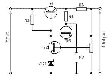
The foldback circuit uses a few more electronic components, including a transistor and a few resistors, but it gives much better protection for the power supply and the circuitry being powered.
The circuit works because as the load increases, an increasing proportion of the voltage between the emitter and ground is dropped across the resistor R3 - as the load becomes smaller the potential divider effect means that more voltage is dropped across R3.
A point is reached when the transistor, Tr3 starts to turn on. When this happens it starts to limit the current.
If the load resistance becomes smaller, then the voltage across R3 increases, turns on Tr3 more and this reduces the current further, folding back the level of current provided.
There are a few equations that can be used to determine the key values of the circuit to provide the required maximum current for the linear voltage regulator, and also the foldback current level on a short circuit.
For the maximum current from the linear voltage regulator:
For the short circuit current of the linear voltage regulator:
The ratio of maximum current over short circuit current is:
Where:
Imax = maximum current of voltage regulator before current limiting
VBE = voltage for the transistor to start to turn on - normally 0.6V
Vreg = output regulated voltage
ISC = current provided when a short circuit is present.

In view of the fact that the regulator sense point occurs after the current sense resistor, any voltage drop across the resistor will not affect the output voltage of the circuit as this will be compensated for by the regulator. (This assumes that there is sufficient voltage across the series pass transistor for it to regulate correctly.) In this way the current sense resistor will not cause any reduction in the voltage output from the power supply regulator circuit.
The power supply current limiter circuit can be incorporated within a variety of different circuits using transistors and FETs as the series pass element. Operational amplifiers can be used as differential amplifiers to give the required voltage reference drive for the output devices.
The main issue with fold-back current limiting is that it does not always work well with non-linear loads. For example if it were to drive an incandescent lamp, where the resistance when it is cool is much lower than it is when hot, the voltage regulator with current limiter would see a very low resistance and would enter the fold-back, not allowing the lamp to heat up and start. Inductive loads can find similar issues - motors, etc have a large start-up current. This means that basic foldback current limiting is not suitable for these types of load in most cases.
Current limiting is a key feature of all power supplies. With electronic devices being left powered up almost permanently and often left unattended, safety features like current limiting are essential in linear power supplies as well as switch mode power supplies.
Fortunately current limiting is easy to implement and does not require the incorporation of many additional electronic components, and if contained within an integrated circuit, the additional cost is not noticeable.
More Circuits & Circuit Design:
Op Amp basics
Op Amp circuits
Power supply circuits
Transistor design
Transistor Darlington
Transistor circuits
FET circuits
Circuit symbols
Return to Circuit Design menu . . .

