
Op Amp Low Pass Filter: active filter circuit design
Low pass filters using operational amplifier or op amp circuits provide an easy and effective method or creating these filters with a minimum of electronic components.
Op-amp Circuits Include:
Introduction
Circuits summary
Inverting amplifier
Summing amplifier
Non-inverting amplifier
Inverting vs non-inverting circuits
Variable gain amplifier
High pass active filter
Low pass active filter
Bandpass filter
Notch filter
Comparator
Schmitt trigger
Multivibrator
Bistable
Integrator
Differentiator
Wien bridge oscillator
Phase shift oscillator
Operational amplifiers or op-amps provide a very effective means of creating active low pass filters providing high levels of performance.
By incorporating the filter elements into the feedback loop of an op amp circuit, it is possible to create a low pass filter very easily created with a minimum number of electronic components and without the need for inductors which can be large and expensive as well as not being nearly as widely available as capacitors and resistors.
Low pass filters using op amp circuits are easy to design and build within a small space and this makes them ideal for many areas of electronic circuit design.
What is a low pass filter
As the name implies, a low pass filter is a filter that passes the lower frequencies and rejects those at higher frequencies.
Low pass filters are used in many applications to limit the bandwidth of a signal. For example a low pass filter may be used prior to an analogue to digital conversion circuit block to limit the top frequencies entering and to prevent aliasing. Similarly they are used with digital to analogue conversion to remove the aliases at high frequencies. They are also used in transmitters to prevent harmonics of the signal being radiated, and similarly they may be used after RF mixers to remove the unwanted high frequencies generated. They can also be sued in very many other areas of electronic circuit design.
In this way, low pass filters are used in many areas of electronic circuit design where the low frequencies are required, but the higher frequencies need to be rejected.

The shape of the curve is of importance with features like the cut-off frequency and roll off being key to the operation.
The cut-off frequency is normally taken as the point where the response has fallen by 3dB as shown.
Another important feature is the final slope of the roll off. This is generally governed by the number of 'poles' in the filter. Normally there is one pole for each capacitor and inductor in a filter.
When plotted on a logarithmic scale the ultimate roll-off becomes a straight line, with the response falling at the ultimate roll off rate. This is 6dB per pole within the filter. This a filter with a single capacitor rolls off at 6dB per octave, but a low pass filter with two capacitors and an inductor would roll off at 18dB per octave.
Traditional passive low pass filters may use resistors and capacitors, or for those with better performance indicators and capacitors can be used. However inductors are expensive and especially at low frequencies they are also to be avoided because of their size.
As a result of this, active low pass filters are a much better option for many areas of electronic circuit design.
What is an active filter
There are both active and passive filters that can be used in electronic circuit design. As the name indicates a passive filter is one that uses only passive electronic components: inductors, capacitors and resistors
An active filter is one that uses active electronic components: namely amplifiers.
Often active filters use op amp circuits as these lend themselves to adding filter components, especially involving the negative feedback loop.
By using an active filter approach, better performance can be obtained: the use of an amplifier such as an operational amplifier prevents following stages loading the filter and impairing its performance.
Also an active filter can have complex poles and zeros without needing to use bulky expensive inductors, making the filter relatively easy to implement using resistors and capacitors as the external electronic components.
A further advantage of an active filter is that the shape of the response, the Q or quality factor, and the frequency can often be set with inexpensive variable resistors. In some active filter circuits, one parameter can be adjusted without affecting the others.
Single pole active low pass filter circuit
The simplest op amp circuit for a low pass filter circuit simply places a capacitor across the feedback resistor. This has the effect as the frequency rises of increasing the level of feedback as the reactive impedance of the capacitor falls.
This form of very simple filter is normally used in instances where a small amount of roll off is required, and this can be achieved using only one extra electronic component.

The break point for this simple type of filter can be calculated very easily by working out the frequency at which the reactance of the capacitor equals the resistance of the resistor. This can be achieved using the formula:
Where:
Xc is the capacitive reactance in ohms
Π is the greek letter and equal to 3.142
f is the frequency in Hertz
C is the capacitance in Farads
The in band gain for these op amp circuits is calculated in the normal way ignoring the effect of the capacitor.
While these op amp circuits are useful to provide a reduction in gain at high frequencies, they only provide an ultimate rate of roll off of 6 dB per octave, i.e. the output voltage halves for every doubling in frequency. This type of filter is known as a one pole filter. Often a much greater rate of rejection is required, and to achieve this it is possible to incorporate a higher performance filter into the feedback circuitry.
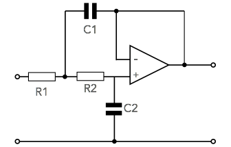
Two pole low pass filter op-amp circuit
Although it is possible to design a wide variety of filters with different levels of gain and different roll off patterns using an operational amplifier and a few additional electronic components. The filter is straightforward, offers single electronic circuit design calculations and provides a good overall 'sure-fire' solution.
The op amp circuit provides unity gain and a Butterworth response (the flattest response in band, but not the fastest to achieve ultimate roll off out of band).
If a different response is required, then it is possible to undertake calculations for these, although the electronic circuit design calculations are rather more complicated.

using an op amp, tow resistors and two capacitors
The calculations for the circuit values are very straightforward for the Butterworth response and unity gain scenario. Critical damping is required for the circuit and the ratio of the resistor and capacitor values determines this.
When choosing the electronic component values, ensure that the resistor values fall in the region between 10 kΩ and 100 kΩ. This is advisable because the output impedance of the circuit rises with increasing frequency and values outside this region may affect the overall performance of the op amp circuit.
Electronic components for active filters
The choice of the electronic components used in an active filter is key to the successful operation of the circuit.
The key issue is that the bandwidth of the filter is correct. Changes in the electronic component values as a result of their tolerance can alter the bandwidth. In some instances this may not be critical, but in others it could be. During the electronic circuit design, this should be assessed and the components chosen accordingly.
Today metal film resistors are available in leaded and surface mount device format. These resistors are not only low noise, but they also can be bought in close tolerance forms. Typically they are available as 1%, 2% or occasionally 5% versions. As there is often little cost difference, using 2% resistors is a good choice.
In terms of the capacitors, electrolytic capacitors are not a good choice. Not only are they polarised but their tolerance is very poor. Typically electrolytic capacitors have a tolerance of -20% and +80%, so they are not at all accurate.
Ceramic capacitors offer a good level of performance and they are normally available in the ranges required. They are also available as both leaded and surface mount devices. Dependent upon the actual dielectric, very high tolerance capacitors are available, although again the actual tolerance will depend upon the application.
Plastic film capacitors are another good choice as many types offer good tolerance levels. However film capacitors are generally only available as leaded devices and not as surface mount devices.
Op amp low pass filters are easy to design, especially when a Butterworth filter type is used as above. More sophisticated designs using different types of filter can also be developed, although the mathematics does become more complicated and decisions need to be made about the optimum type of response and filter to be used. For most applications, the basic Butterworth provides excellent filter performance.
More Circuits & Circuit Design:
Op Amp basics
Op Amp circuits
Power supply circuits
Transistor design
Transistor Darlington
Transistor circuits
FET circuits
Circuit symbols
Return to Circuit Design menu . . .

