
Active op amp high pass filter circuit
Op amp high pass filters are very easy to design using a few electronic components & with straightforward equations for a Butterworth response.
Op-amp Circuits Include:
Introduction
Circuits summary
Inverting amplifier
Summing amplifier
Non-inverting amplifier
Inverting vs non-inverting circuits
Variable gain amplifier
High pass active filter
Low pass active filter
Bandpass filter
Notch filter
Comparator
Schmitt trigger
Multivibrator
Bistable
Integrator
Differentiator
Wien bridge oscillator
Phase shift oscillator
Op amp high pass filters are easy to implement using just a few electronic components being used in a variety of electronic devices and circuits to eliminate hum and other noise.
Although any form of filter response can be chosen, the Butterworth response simplifies the equations and the electronic design process producing the electronic component values can be undertaken in a very short while.
Despite the ease of design, op amp high pass filters are able to provide a high level of performance from just a relatively small number of electronic components, and this makes them a very attractive proposition for low frequency circuits.
What is a high pass filter
As the name implies, a high pass filter is a filter that passes the higher frequencies and rejects those at lower frequencies.
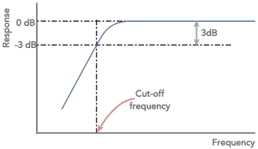
The shape of the curve is of importance. One of the most important features is the cut-off frequency. This is normally taken as the point where the response has fallen by 3dB.
Another important feature is the final slope of the roll off. This is generally governed by the number of 'poles' in the filter. Normally there is one pole for each capacitor or inductor in a filter.
When plotted on a logarithmic scale the ultimate roll-off becomes a straight line, with the response falling at the ultimate roll off rate. This is 6dB per pole within the filter.
The advantage of using an op amp circuit for the high pas filter, is that a multiple pole circuit can be made using just capacitors and resistors, rather than inductors that might otherwise be needed.
Single pole op amp high pass filter
The simplest circuit high pass filter circuit using an operational amplifier can be achieved by placing a capacitor in series with one of the resistors in the amplifier circuit as shown. The capacitor reactance increases as the frequency falls, and as a result this forms a CR low pass filter providing a roll off of 6 dB per octave.

The cut off frequency or break point of the filter can be calculated very easily by working out the frequency at which the reactance of the capacitor equals the resistance of the resistor. This can be achieved using the formula:
Where:
Xc is the capacitive reactance in ohms
Π is equal to 3.142
f is the frequency in Hertz
C is the capacitance of the capacitor in Farads
Two pole active high pass filter
Although it is possible to design a wide variety of filters with different levels of gain and different roll off patterns using operational amplifiers, the filter described on this page will give a good sure-fire solution. It offers unity gain and a Butterworth response (the flattest response in band, but not the fastest to achieve ultimate roll off out of band).

The calculations for the circuit values are very straightforward for the Butterworth response and unity gain scenario. Critical damping is required for the circuit and the ratio of the resistor vales determines this.
When choosing the values, ensure that the resistor values fall in the region between 10 kΩ and 100 kΩ. This is advisable because the output impedance of the circuit rises with increasing frequency and values outside this region may affect the performance.
Electronic components for high pass active filters
The choice of the electronic components used in a high pass active filter is key to the successful operation of the circuit.
It is important that the bandwidth of the high pass filter is correct. Changes in the electronic component values as a result of their tolerance can alter the bandwidth. In some instances this may not be critical, but in others it could be. During the electronic circuit design process, this should be assessed and the electronic component values and types chosen accordingly.
Today metal film resistors are available in leaded and surface mount device formats. These resistors are not only low noise, but they also can be bought in close tolerance forms. Typically they are available as 1%, 2% or occasionally 5% versions. As there is often little cost difference, using 2% resistors is a good choice. Other types of resistor may also be used if available, but check the tolerance is suitable for the particular electronic circuit design in question.
In terms of the capacitors, aluminium electrolytic capacitors are not a good choice. Not only are they polarised but their tolerance is very poor. Typically aluminium electrolytic capacitors have a tolerance of -20% and +80%, so they are not at all accurate. Tantalum electrolytic capacitors may also not be suitable. Their tolerance is better, but generally not as good as needed and also they are polarised.
Ceramic capacitors offer a good level of performance and they are normally available in the ranges required. They are also available as both leaded and surface mount devices. Dependent upon the actual ceramic dielectric, very high tolerance capacitors are available, although again the actual tolerance needed will depend upon the application.
Plastic film capacitors are another good choice as many types offer good tolerance levels. However film capacitors are generally only available as leaded devices and not as surface mount devices.
When using the op amp active high pass filter higher levels of attenuation and steeper roll-of can be achieved by cascading a number of circuits. The design can also be altered to accommodate different forms of filter, although the calculations do become more difficult.
More Circuits & Circuit Design:
Op Amp basics
Op Amp circuits
Power supply circuits
Transistor design
Transistor Darlington
Transistor circuits
FET circuits
Circuit symbols
Return to Circuit Design menu . . .

