
Comparator Circuits & Op-Amps
The comparator circuit is very useful for comparing two voltages and detecting the larger or smaller - we look at comparators in general and the issues of using an op amp as a comparator.
Op-amp Circuits Include:
Introduction
Circuits summary
Inverting amplifier
Summing amplifier
Non-inverting amplifier
Inverting vs non-inverting circuits
Variable gain amplifier
High pass active filter
Low pass active filter
Bandpass filter
Notch filter
Comparator
Schmitt trigger
Multivibrator
Bistable
Integrator
Differentiator
Wien bridge oscillator
Phase shift oscillator
Circuits that compare two voltages and give a digital output dependent upon the comparison of the two voltages are often used within electronic circuit design.
For a comparator circuit, a high gain amplifier is needed so that even small changes on the input result in the output level firmly switching.
Operational amplifiers are used in many electronic circuit designs, but specific comparator chips provide far better performance.
Comparator applications
There are very many uses for comparator circuits within electronic circuit design.It is often necessary to be able to detect a certain voltage and switch a circuit according to the voltage that has been detected.
One example could be for use in a temperature sensing circuit. This might produce a variable voltage dependent upon the temperature. It may be necessary to switch heating on when the temperature falls below a given point and this can be achieved by using a comparator to sense when the voltage proportional to the temperature has fallen below a certain value.
For these and many other uses, a circuit known as a comparator can be used.
What is a comparator?
As the name comparator implies these electronic components and circuits are used to compare two voltages.
When one is higher than the other the comparator circuit output is in one state, and when the input conditions are reversed, then the comparator output switches to the other state.
The comparator essential consists of a high gain amplifier that has a differential input - one inverting input and one non-inverting input.
In terms of operation the comparator switches between high and low dependent upon the state of the inputs. If the non inverting input is higher than the inverting one, then the output is high. If the non-inverting input is lower than the inverting one then the output is high.

Should I use an op-amp as a comparator?
We've all used op amps as comparators. They are often available to use for one reason or another, and the circuit requirements are not particularly demanding, so we use an op amp.
Whilst it is easy to use an operational amplifier as a comparator, especially when it may be easy to use one if a chip containing multiple op amps has one spare. However it is not always advisable to adopt this approach.
The op amp may not always function correctly, or it may not give the optimum performance. That said, when the application is not demanding, it is always tempting to use these electronic components because they may already be available.
The performance of comparator chips and op amps is quite different in a number of aspects:
Op amp latch-up: Under some conditions, especially when an op amp is being driven hard it is possible for it to latch up, i.e. even when the input changes, the output remains the same. Comparators are designed to operate in this mode and should never latch up.
This is one key area where using a comparator rather than an op amp can be a distinct advantage.
Open loop operation: Operational amplifiers are designed to be used in a closed loop mode and their circuit is optimised for this type of scenario. Their operation is not characterised in open loop mode.
Digital vs analogue: Operational amplifiers are essential analogue components and their internal circuitry is designed to operate in this region. Comparators are designed to be operated as a logic function, i.e. in a digital mode.
This means that operational amplifiers are best when they are operating in an analogue mode with the output not hitting the rails, whereas comparators are not so good at operating in a linear mode, and are far better at operating with logic levels.
Output stages: The output stages of operational amplifiers and comparators are very different. Typically operational amplifiers have a linear output, often operating in a complementary symmetry fashion to give optimum linear performance for the output.
Comparators often have an open collector output suitable for driving into digital interfaces. They are designed to interface with logic circuitry, providing a logic input from a comparison of analogue voltages.
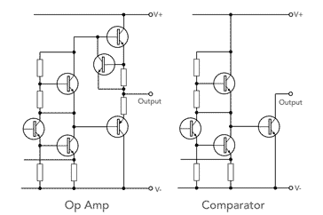
Comparison of op amp and comparator output circuitry Response times: Comparators are optimised to provide very fast response and switching times. Slew rates are fast and provide optimum performance.
Operational amplifiers are not optimised for these characteristics. They tend to be much slower electronic components optimised for linear operation rather than speed.
Output voltage & saturation voltage: Comparators are typically able to drive to within small limits of the rail voltages. This is required for good switching of logic circuits. Op amps will not be able to drive hard to the rails as they have a certain saturation voltage - this may lead to poor switching of logic circuits.
In view of these factors, it is always preferable to utilise a comparator chip where this type of operation is envisaged, but many of us use op amps as comparators and get away with it.
If you still use an op amp, it will probably work OK for an experimental or other non-critical circuit, but if one is used in a circuit that is used in a mass produced circuit, it is quite likely to start giving problems at some stage. Producing an electronic circuit in quantity always brings any design weaknesses tot he front sooner or later, and if an op amp is used as a comparator, this could be an issue that will show itself in the middle of a large production run.
Operational amplifier comparator
It is possible to use an op amp as a comparator as it fulfils the basic requirements for the function.
In operation the operational amplifier goes into positive or negative saturation dependent upon the input voltages. As the gain of the operational amplifier will generally exceed 100 000 the output will run into saturation when the inputs are only fractions of a millivolt apart.
Although op amps are widely used as comparator, special comparator chips are far better.These specific comparator chips offer very fast switching times, well above those offered by most op-amps that are intended for more linear applications. Typical slew rates are in the region of several thousand volts per microsecond, although more often figures of propagation delay are quoted.
A typical comparator circuit will have one of the inputs held at a given voltage. This may often be a potential divider from a supply or reference source. The other input is taken to the point to be sensed.

Within this diagram, the switching voltage is generated by the potential divider consisting of R1 and R2. This sets the voltage at one input of the comparator – in this case the inverting input. The non-inverting input of this circuit is connected to the point requiring sensing. When the voltage on this point rises above the reference voltage the output of the comparator will go high, and when it falls below the reference voltage the output will go low.
Typically the comparator will be driven from the same voltage rails as those of the system. For 5V logic the comparator would typically be driven from a 5V rail.
Op amp comparator notes
There are a number of points to remember when using comparator circuits. There are some differences between the normal operational amplifier circuits and the comparator circuits that must be considered during any electronic circuit design.
- Ensure differential input not exceeded: As there is no feedback the two inputs to the circuit will be at different voltages. Accordingly it is necessary to ensure that the maximum differential input is not exceeded. All possibilities of the circuit state should be considered at the electronic circuit design stage.
- Input current change: Again as a result of the lack of feedback the load presented by the comparator to the source will change. Particularly as the circuit changes there will be a small increase in the input current. For most circuits this will not be a problem, but if the source impedance is high it may lead to a few unusual responses. This should be taken into account during the electronic circuit design.
- Input signal noise: The main problem with this circuit is that new the changeover point, even small amounts of noise will cause the output to switch back and forth. Thus near the changeover point there may be several transitions at the output and this may give rise to problems elsewhere in the overall circuit. The solution to this is to use a Schmitt Trigger.
Read more about the . . . . Schmitt trigger circuit.
Where comparator function is required, it is best to use comparator chip: Where a comparator function is required, it is always preferable to use a comparator chip if at all possible. If one of these electronic components is not available and an op amp needs to be used, then be careful not to overload the input so that latch up occurs.
Use of a comparator chip
When there is a need for a comparator circuit, it is always best to opt for a specific comparator chip as the basis of the circuit.
Comparator chips are much better at handling switching between two values and may often have output stages that can more easily interface with logic than analogue operational amplifiers.
In terms of the basic circuit operation, the main difference is that most comparators have an open collector output and require an external pull-up resistor or other circuity.
Operational amplifiers are very cheap, and very widely available. Comparators are not quite so cheap and not quite as freely available as these electronic components tend to be used a little less and may be a little more expensive, but not greatly so. There should be no issues with using them.
More Circuits & Circuit Design:
Op Amp basics
Op Amp circuits
Power supply circuits
Transistor design
Transistor Darlington
Transistor circuits
FET circuits
Circuit symbols
Return to Circuit Design menu . . .

