
Op Amp Active Bandpass Filter Design
Operational amplifiers, op-amps are able to provide a simple method for crating an active bandpass filter circuit.
Op-amp Circuits Include:
Introduction
Circuits summary
Inverting amplifier
Summing amplifier
Non-inverting amplifier
Inverting vs non-inverting circuits
Variable gain amplifier
High pass active filter
Low pass active filter
Bandpass filter
Notch filter
Comparator
Schmitt trigger
Multivibrator
Bistable
Integrator
Differentiator
Wien bridge oscillator
Phase shift oscillator
Bandpass filters are used in many applications where a single band of frequencies is required, and those above and below need to be rejected.
Operational amplifiers are able to provide a convenient method of creating bandpass filters or many other types of filter.
The op amp bandpass filter can be created using a relatively small number of components and gives a good level of performance for many applications. Although when using a single op amp, the bandpass filter performance is a little limited, further stages or more complex topologies can be used if required.
What is a bandpass filter
As the name implies a bandpass filter is one where only a given band of frequencies is allowed through.
All frequencies outside the required band are attenuated.
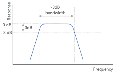
There are two main areas of interest in the response of the filter. These are the pass-band where filter passes signals and the stop-band where signals are attenuated. As it is not possible to have an infinitely steep roll off, there is an area of transition outside the pass-band where the response is falling but has not reached the required out of band attenuation.
Op amp active bandpass filter circuit
The design of band pass filters can become very involved even when using operational amplifiers. However it is possible to simplify the design equations while still being able to retain an acceptable level of performance of the operational amplifier active filter for many applications.
The circuit and design equations represent a good balance between performance and ease of circuit design.

From the circuit it can be seen that apart from the operational amplifier itself, the circuit comprises of two capacitors and three resistors.
Where:
H0 = gain
ω0 = 2 π f
Practical filter design notes
When only one operational amplifier chip is used in the bandpass filter circuit, the gain should be limited to five or less, and the Q to less than ten.
If it becomes necessary to improve the performance in terms of gain or shape factor, further stages can be added.
It is also worth noting when designing and implementing an op amp bandpass filter of this type, that high tolerance / stability components should be used for both the resistors and the capacitors. Any change from the required values can cause the performance to degrade.
This op amp bandpass filter gives a good account of itself and can be used in many instances. It provides a useful level of performance, although it does have some limitations. If these can be accepted, then it is an easy and low cost method of implementing a fixed bandpass fiter.
More Circuits & Circuit Design:
Op Amp basics
Op Amp circuits
Power supply circuits
Transistor design
Transistor Darlington
Transistor circuits
FET circuits
Circuit symbols
Return to Circuit Design menu . . .

