
What is a Vector Network Analyzer, VNA: & how it works
Understand what an RF Vector Network Analyzer, VNA is, how it works and what it does in measuring the response of a network as vector: real & imaginary parameters so that its performance can be characterised.
RF vector network analyzer includes:
What is a VNA
VNA calibration
VNA specifications
Scalar analyzer
RF network analyzers are vital items of test instrumentation for RF design laboratories as well as many manufacturing and service areas.
Although mainly focussed on research and development, RF network analyzers are able to provide vital insights into the operation and performance of RF networks of all types.
The RF network analyzer provides a stimulus for the network and then monitors the response. In this way the operation and performance can be seen and assessed for its suitability.
RF network analyzers can be used for all RF and microwave frequencies - some network analyzers can operate well into the microwave region.
Types of RF network analyzer
Within the broad scope of RF network analyzers, there are various types of instrument which can be bought and used. These types of RF network analyzer are very different, but they are all able to measure the parameters of RF components and devices but in different ways:
- Scalar network analyzer (SNA): The scalar network analyzer, SNA is a form of RF network analyzer that only measures the amplitude properties of the device under test - i.e. its scalar properties. In view of this it is the simpler of the various types of analyser.
- Vector network analyzer (VNA): The VNA network analyzer is a more useful form of RF network analyzer than the SNA as it is able to measure more parameters about the device under test. Not only does the it measure the amplitude response, but it also looks at the phase as well. As a result VNA network analyzer may also be called a gain-phase meter or an Automatic Network Analyzer.
- Large Signal Network Analyzer (LSNA): The large signal network analyzer, LSNA is a highly specialised for of RF network analyser that is able to investigate the characteristics of devices under large signal conditions. It is able to look at the harmonics and non-linearities of a network under these conditions, providing a full analysis of its operation. A previous version of the Large Signal Network Analyser, LSNA was known as the Microwave Transition Analyzer, MTA.
The various types of RF network analyzer are quite different in their make-up and the way in which they are able to make measurements. The scalar network analyzer is the least expensive, although not cheap, but it also provides the least information. The VNA network analyzer is able to provide considerably more information, but these RF network analyzers are also considerably more expensive.
Difference between RF network analyzers and spectrum analyzers
Although there are many similarities between RF network analyzers and spectrum analyzers, there are also several major differences, especially in the types of measurements that are made. In particular they make very different types of measurement. In the first instance a spectrum analyzer is intended for analysing the nature of signals that are fed into them. A network analyzer, on the other hand generates a signal and uses this to analyze a network or device.
RF Network analyzers are used to measure components, devices, circuits, and sub-assemblies. An RF network analyzer will contain both a source and multiple receivers. It will display amplitude and often phase information (frequency or power sweeps) and normally in a ratio format. An RF network analyzer looks for a known signal, i.e. a known frequency, at the output of the device under test, since it is a stimulus response system. With vector-error correction, network analyzers provide much higher measurement accuracy than spectrum analyzers.
By contrast to RF network analyzers, spectrum analyzers are normally used to measure the characteristics of a signal rather than a device. The parameters measured may include: signal or carrier level, sidebands, harmonics, phase noise, etc. They are most commonly configured as a single channel receiver, without a source. Because of the flexibility needed to analyze signals, spectrum analyzers generally have a much wider range of IF bandwidths available than most RF network analyzers.
Spectrum analyzers can be used for testing networks such as filters. To achieve this they need tracking generator. When used in this way, spectrum analyzers can be used for scalar component testing (magnitude versus frequency, but no phase measurements). With spectrum analyzers, it is easy to get a trace on the display, but interpreting the results can be much more difficult than with a network analyzer.
Concept of vector network analyzer: how it works
The vector network analyzer utilises the concept of measuring the transmitted and reflected waves as a signal passes through a device under test.
Measuring the transmitted and reflected signals across the band of interest, and often beyond, enables the characteristics of a device to be determined. If both transmitted and reflected signals are used to characterise the input and also the output then the device can be fully characterised. This can form a key part of any design or test for an RF circuit.

• Reflection parameters
When power enters an RF network, some enters the network, but dependent upon the impedance match, some of the power is reflected back to thee source.
Note on Standing Wave Ratio, SWR & VSWR:
Standing waves are often associated with RF feeders, and they are generated when there is a mismatch between the feeder impedance and the load impedance. At th emismatch, power is reflected and the combined voltages and currents of the forward and reflected power form standing waves along the feeder.
Read more about Voltage Standing Wave Ratio, VSWR.
The reflection coefficient, Γ is is one of the key parameters.
Where:
Γ = reflection coefficient
Vreflected = voltage of the reflected wave
Vincident = voltage of the forward or incident wave
ZL = load impedance
Z0 = feeder characteristic impedance
Return loss is another way of expressing the reflection characteristics:
• Transmission characteristics
The transmission characteristics of the RF network are equally important in the vector network analyzer as these determine how power passes through the network.
The transmission coefficient, T can be expressed:
Insertion loss (- values) or gain (+ values) can be expressed as:
Magnitude and phase
The key element of the vector network analyzer, VNA, is that it can measure both amplitude and phase. While an amplitude only measurement is much simpler to make, and can be undertaken by less complicated instruments. This may be quite sufficient for many instances. For example when the only consideration is the gain of an amplifier over a certain bandwidth, or the amplitude response of a filter is needed
However a measurement that includes phase as well as amplitude enables far more to be discovered about the device under test as phase is a critical element in network analysis. This is because a complete characterization of devices and networks involves measurement of phase as well as magnitude.
Only with a knowledge of phase and magnitude from a vector network analyser can circuit models be developed that will enable complete simulation to be undertaken. This will enable matching circuits to be designed based on conjugate matching techniques. Time-domain characterization requires magnitude and phase information to perform the inverse-Fourier transform. Also, phase data is required to perform vector error correction.
Vector network analyzer block diagram
In order to understand more fully how a vector network analyzer operates, it is useful to see a basic block diagram of the test instrument.
The diagram shows the very basic blocks of the VNA including the signal ports, the signal separation blocks, the receiver detector, and finally the processor and display.
The simplified block diagram for the vector network analyzer is provided to give an overall guide to the way the test instrument operates. Any actual VNA will be far more complicated, but contain these essential building blocks.

The diagram shows a high level block diagram of an RF network analyzer showing the main circuit blocks:
- Processor and display: This area of the RF network analyzer acts as the human machine interface, displaying the results in the required fashion - it is possible to display the results of the network analysis in a variety of formats including Smith chart, Cartesian format, real and imaginary values. The most common output from a vector network analyzer is in a Smith chart format as this concisely shows the attributes of the network.
- Signal source: The signal source(s) of the VNA provide the stimulus for the RF network. These oscillators are contained within the VNA and are able to sweep over the frequency range of the test instrument.
- Receiver & detector: This block of the RF network analyzer receives the signals from the signal separators and processes them in terms of reflected and transmitted waves compared to the incident wave. These results are passed into the processor and display.
- Ports: These are the elements of the VNA that connect directly to the device under test. They typically have two connections to the DUT, one at the input and one at the output, etc. Some VNAs may have more ports for use with systems that have multiple connections.
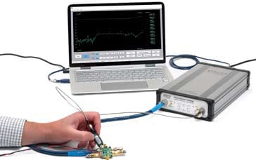
The VNA has precision connectors on the front panel of the unit itself and then precision cables are used to connect these to the device under test. Precision cables are required because the phase and loss of a standard cable would vary too much with even slight movement, etc.
To test the device, a variable frequency signal is generated within the vector network analyzer and the output is switched to test the DUT in either one direction or the other. In this case the left hand side on the diagram is selected. The signal passes to the splitter where one output is used as the reference signal for the receiver and the other side is passed to a direction coupler and then into the DUT via the external connection on the VNA and the precision cables.
Power passes through the directional coupler (directional coupler 1) to the DUT, but the third port detects the reflected power and this is connected to the receiver again.
Power that passes through the device under test is sampled by directional coupler 2 and this signal is connected to the receiver.
Apart from generating a signal to power the device under test, the signal source also has an output that is connected to the receiver. This enables phase information to be gained from the detected signals. Currently vector network analyzers will make significant use of digital signal processing, and there much of the receiver and detector section will be undertaken in digital format.
The signals are processed by the receiver are then fed to the processor and display. This section will again make heavy use of microprocessor technology to provide the control, functionality and user friendly displays that are needed for modern test instrumentation.
Although this very simplified example of an RF network analyzer shows two ports, some vector network analyzers may use more ports for systems where many different signal paths exist.
RF network analyzers can be very expensive items of test equipment. However they are invaluable in the design of RF networks - particularly filters and any other items where the RF performance of the item needs to be accurately assessed. In this way it is possible to fully understand what is happening and ensure that the overall design operates correctly.
More Test Topics:
Data network analyzer
Digital Multimeter
Frequency counter
Oscilloscope
Signal generators
Spectrum analyzer
LCR meter
Dip meter, GDO
Logic analyzer
RF power meter
RF signal generator
Logic probe
PAT testing & testers
Time domain reflectometer
Vector network analyzer
PXI
GPIB
Boundary scan / JTAG
Data acquisition
Return to Test menu . . .


