Synchronous AM demodulation provides some significant improvements over the simple diode detector.
The improvement in performance of synchronous detectors requires the use of additional components and sophistication and in turn this increases the cost. As a result synchronous detectors are generally only used in high performance receivers where cost is less of an issue.
Today, with the widespread use of integrated circuits, it is easy to incorporate the components for a synchronous detector in an IC at little additional cost. However earlier low cost AM broadcast radios tended to be made from discrete components where the additional circuitry for a synchronous detector would have added significant cost and therefore they were rarely used.
What is AM synchronous demodulation?
The simplest form of detection for an amplitude modulated signal utilises a simple diode rectifier. To achieve improved performance a form of demodulation known as synchronous demodulation can be used.
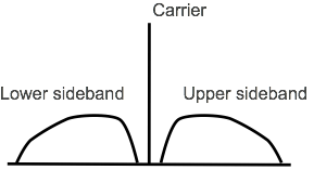
When looking at the synchronous demodulation of an AM signal, it is first useful to look at the spectrum of an amplitude modulated signal. It can be seen that it comprises a carrier with the two sidebands carrying the audio or other information spreading out either side. These two sidebands are reflections of each other. The aim of the demodulation process is to extract the information contained within the sidebands with as little distortion as possible.
Amplitude Modulation Spectrum
For synchronous demodulation, a mixer is used. The incoming signal is fed into the signal input of the mixer, and a local oscillator signal on the same frequency as the carrier of the incoming signal is fed into the other. This mixing process converts the carrier to a 0Hz signal and the sidebands to their base band frequency band, i.e. it reconstitutes the audio.
As the carrier has a frequency of 0Hz, it appears as a DC voltage on the output - the DC level will depend on the phase between the carrier and the local oscillator. The sidebands of the AM signal will appear relative to zero frequency, i.e. as the original audio or other modulating signal.
Synchronous demodulation
Advantages of synchronous AM detection
At the expense of additional components and cost, the synchronous AM demodulator provides a number of advantages in terms of performance.
Reduced effects of selective fading: For HF communications, and in particular broadcasting, a particular annoyance is the fading that occurs. In some circumstances this can affect different sections of the bandwidth of an AM signal differently.
It is possible for the level of the carrier to fade by ten to fifteen dB relative to the sidebands, and this makes envelope detection difficult and it gives rise to significant levels of distortion. As synchronous demodulation techniques generate their own carrier, the effects of selective fading are considerably reduced making for a much better listening experience.
Reduce levels of distortion: The diode AM demodulator provides very high levels of distortion. Synchronous AM demodulation offers much lower levels of distortion and as a result provides a much better rendering of the original modulation. Distortion arises from many factors including the turn on voltage required for the diode in an envelope detector, selective fading as mentioned above and poor tuning.
Signal level: When diode detectors are used it is necessary to have a sufficient level of signal present to overcome the diode forward bias. For synchronous detectors this is not an issue because the mixer used within the detector can operate down to very low levels.
Improved signal to noise ratio: In view of the use of synchronous methods, the circuit is able to provide an improvement in sensitivity.
Types of synchronous detector
Although all synchronous detectors or synchronous demodulators use the same basic concept of using a local oscillator on the same frequency as the incoming carrier, and using this mix with the incoming signal to extract the audio, there are several methods of achieving this.
Filter method: This method of providing synchronous detection is probably the most obvious. It entails using a narrow band filter to extract the carrier and then using this to mix with the overall signal.
This method requires the receiver to be tuned to exactly the required frequency to enable the carrier to pass through the narrow band filter. Fortunately receiver stability is not an issue these days and once tuned, it should remain on the required frequency, but tuning is critical for this method and it is not particularly successful.
Phase locked loop: Phase locked loops are particularly useful in many RF applications. This form of synchronous detector uses a phase locked loop with a narrow loop filter to lock on to the carrier and replicate a signal on exactly the same frequency. This signal is then used as the local oscillator signal to mix with the incoming AM signal to extract the audio.
This form of synchronous detector works well and the approach has been used in many radio receivers.
Limiting amplifier: Another method of creating a synchronous detector is to use a limiting amplifier to generate the carrier. Some of the signal is taken from the IF amplifier chain of the receiver and applied to a circuit with a very high gain. The amplifier will limit and when an AM signal is present this will remove any amplitude variation, i.e. the modulation, and leave only the carrier. High gain limiting amplifier synchronous detector
This is a very elegant method of creating a synchronous detector and one that is not only simple but works effectively, not requiring complex filters or even a phase locked loop.
The circuit arrangement for the limiting amplifier form of synchronous detector comprises the normal IF amplifier chain. The output from the IF amplifier is applied to a mixer. The output from the IF amplifier is also applied to a limiting amplifier, and the output from this is applied to the local oscillator input of the mixer. The output is then the recovered audio that can be amplifier by an audio amplifier in the normal way.
Whatever method of synchronous detection is used, it provides some significant advantages over a diode envelope detector in terms of reduced distortion, increased immunity to selective fading, and low signal performance.
Fact of the day: It was on this day in 1874 that Guglielmo Marconi was born. He was known as the person who was one of the first people to see the commercial value of radio and as a result push forward its development. Then in 1990, the Hubble Space Telescope was first deployed in space.
Quote:Mathematics is the key and door to the sciences. Galileo Galilei
Point to ponder: The degree of technical competence is inversely proportional to the level of management.