
What is Radio Receiver Dynamic Range
There are man important parameters associated with radio receiver operation - one of the key parameters is dynamic range.
Radio Dynamic Range Includes:
What is dynamic range
In today’s radio communications environment the dynamic range of the receiver is important because it is necessary to receive both strong and weak signals, and weak signals in the presence of strong ones.
With vast numbers of radios in existence, there are many signals being transmitted all the time - for example, mobile phones need to accommodate both weak and strong signals at the same time. The RF circuit design of the radio will determine the factors that govern the dynamic range, so it is important to consider these at the earliest concept stages.
Whilst dynamic range is very important for radio receivers and radio communications applications, it is also important in many other areas from photographic cameras to audio mixers and many other items where there are many different input levels that have to be accommodated.
Although some of the parameters will change according to the equipment being considered, the basic concept of dynamic range remains the range over which the equipment can successfully handle the incoming signals.
What is dynamic range?
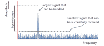
The dynamic range of a radio receiver is essentially the range of signal levels over which it can operate.
It can help to have a definition of the dynamic range of a radio.
Radio receiver dynamic range definition:
The dynamic range of a radio receiver is probably best defined as the range of input levels over which the radio receiver can successfully receive the required signals.
There are many parameters associated with the receiver dynamic range that are important for radio communications applications of all forms.
The low end of the range is governed by its sensitivity whilst at the high end it is governed by its overload or strong signal handling performance. That said there are several different conventions that are used for measuring the receiver dynamic range.
Specifications generally use figures based on either the inter-modulation performance or the blocking performance. Unfortunately it is not always possible to compare one set with another because dynamic range like many other parameters can be quoted in a number of ways.
However to gain an idea of exactly what the dynamic range of a radio receiver means it is worth looking at the ways in which the measurements are made to determine the range of the radio receiver.
Sensitivity
The first specification to investigate is the sensitivity of a receiver. The main limiting factor in any radio receiver is the internal noise that is generated. For many radio communications applications either the signal to noise ratio or the noise figure is used.
However for dynamic range specifications a figure called the minimum discernible signal (MDS) is often used. This is normally taken as a signal equal in strength to the noise level.
As the noise level is dependent upon the bandwidth used, this also has to be mentioned in the specification. Normally the level of the level of the MDS is given in dBm i.e. dB relative to a milliwatt and typical values are around -135 dBm in a 3 kHz bandwidth.
Strong signal handling
Although the sensitivity is important the way in which a radio receiver handles strong signals is also very important.
There are several specifications that may be important in dynamic range specifications:
Third order products: Problems occur when harmonics of in-band signals mix together. It is found that a comb of signals can be produced as shown below, and these may just fall on the same frequency as a weak and interesting station, thereby masking it out so it cannot be heard.
It is simple to calculate the frequencies where the spurious signals will fall. If the input frequencies are f1 and f2, then the new frequencies produced will be at 2f1 - f2, 3f1 - 2f2, 4f1 - 3f2 and so forth. On the other side of the two main or original signals products are produced at 2f2 - f1, 3f2 - 2f2, 4f2 - 3f1 and so forth as shown in the diagram. These are known as odd order inter-modulation products. Two times one signal plus one times another makes a third order product, three times one plus two times another is a fifth order product and so forth. It can be seen from the diagram that the signals either side of the main signals are first the third order product, then fifth, seventh and so forth.
To take an example with some real figures. If large signals appear at frequencies of 30.0 MHz and 30.01 MHz, then the inter-modulation products will appear at 30.02, 30.03, 30.4 ...MHz and 29.99, 29.98, 29.97 ..... MHz.

The spectrum of intermodulation products from two signals Blocking: Another problem that can occur when a strong signal is present is known as blocking. As the name implies it is possible for a strong signal to block or at least reduce the sensitivity of a radio receiver. The effect can be noticed when listening to a relatively weak station and a nearby transmitter starts to radiate, and the wanted signal reduces in strength. The effect is caused when the front-end RF amplifier starts to run into compression. When this occurs the strongest signal tends to "capture" the RF amplifier reducing the strength of the other signals. The effect is the same as the capture effect associated with FM signals.
This aspect of the radio receiver performance is very important in a large number of radio communications applications from mobile phones to strategic radio systems.
The amount of blocking is obviously dependent upon the level of the signal. It also depends on how far off channel the strong signal is. The further away, the more it will be reduced by the front end tuning and the less the effect will be. Normally blocking is quoted as the level of the unwanted signal at a given offset (normally 20 kHz) to give a 3 dB reduction in gain.
Intercept point: In the ideal world the output of an RF amplifier would be proportional to the input for all signal levels. However RF amplifiers only have a limited output capability and it is found that beyond a certain level the output falls below the required level because it cannot handle the large levels required of it. This gives a characteristic like that shown below. From this it can be seen that RF amplifiers are linear for the lower part of the characteristic, but as the output stages are unable to handle the higher power levels the signals starts to become compressed as seen by the curve in the characteristic.

Characteristic curve for an amplifier showing overload area The fact that the RF amplifier is non-linear does not create a major problem in itself. However the side effects do. When a signal is passed through a non-linear element there are two main effects which are noticed. The first is that harmonics are generated. Fortunately these are unlikely to cause a major problem. For a harmonic to fall near the frequency being received, a signal at half the received frequency must enter the RF amplifier. The front end tuning should reduce this by a sufficient degree for it not to be a noticeable problem under most circumstances.
The other problem that can be noticed is that signals mix together to form unwanted products. These again are unlikely to cause a problem because any signals which could mix together should be removed sufficiently by the front end tuning. Instead problems occur when harmonics of in-band signals mix together.
Dynamic range specifications
When looking at dynamic range specifications, care must be taken when interpreting them. The MDS at the low signal end should be viewed carefully, but the limiting factors at the top end show a much greater variation in the way they are specified.
Where blocking is used a reduction of 3 dB sensitivity is normally specified, but in some cases may be 1 dB used. Where the inter-modulation products are chosen as the limiting point the input signal level for them to be the same as the MDS is often taken. However whatever specification is given, care should be taken to interpret the figures as they may be subtlety different in the way they are measured from one receiver to the next.
To gain a feel for the figures which may be obtained where inter-modulation is the limiting factor figures of between 80 and 90 dB range are typical, and where blocking is the limiting factor figures around 115 dB are generally achieved in a good radio receiver used for professional radio communications applications.
Designing for optimum dynamic range performance
It is not an easy task to design a highly sensitive radio receiver that also has a wide dynamic range. The RF circuit design requires the careful balance of many differnet parameters to obtain the optimum performance. However this is an important requirement for many radio communications systems, particularly where mobile radio communications units may come into close proximity with each other.
To achieve the required level of performance a number of methods can be used.
- Front end noise performance: The RF circuit design of the front-end stage of the radio receiver is the most critical in terms of noise performance. It should be optimised for noise performance rather than gain. Input impedance matching is critical for this. It is interesting to note that the optimum match does not correspond exactly with the best noise performance. The electronic components including the active device should be selected for their noise performance.
- Front end output capability : The front end amplifier should also have a relatively high output capability to ensure it does not overload. The RF design must provide sufficient output capability, whilst not generating high levels of noise.
- High level mixer: The mixer operation is one of the key electronic components to ensure a good dynamic range and overload performance. The RF design of the radio should ensure that the mixer is not overloaded. To achieve this there should not be excessive gain preceding it. Also a high level mixer should also be used (i.e. one designed to accept a high-level local oscillator signal). In this way it can tolerate high input signals without degradation in performance.
- Receiver later stages: The RF circuit design should ensure the later stages of the receiver can tolerate the level of signals likely to be encountered when strong signals are being received. It is relatively easy to calculate the maximum signal levels that occur in each stage of the receiver, and then ensure that these can be accommodated by the RF design. In these stages the noise performance is not as important, and therefore high levels of current flow can be used to ensure the required signal levels can be accommodated.
- Automatic gain control: The incorporation of a good AGC system into the RF design also helps prevent overloading and the generation of unwanted spurious signals. By applying a voltage dependent upon the signal level to some of the earlier stages in the receiver, it is possible to ensure the latter ones on the RF design do not become overloaded. The circuit design for the AGC can become rather involved as different time constants within the AGC loop may be required to provide the optimum control for different types of modulation: AM, SSB, etc.
These are just a few of the issues that should be taken into consideration during the RF circuit design of any form of receiver that requires a high dynamic range performance.
A radio receiver, whether it is a traditional radio receiver for short wave reception or a mobile phone, or any other form of receiver will be able to handle the exacting conditions much better if it has a good dynamic range performance.
Whilst sensitivity is required for many applications, this is of little use if strong nearby transmissions both in frequency and location mean that the sensitivity cannot be realised.
More Essential Radio Topics:
Radio Signals
Modulation types & techniques
Amplitude modulation
Frequency modulation
OFDM
RF mixing
Phase locked loops
Frequency synthesizers
Passive intermodulation
RF attenuators
RF filters
RF circulator
Radio receiver types
Superhet radio
Receiver selectivity
Receiver sensitivity
Receiver strong signal handling
Receiver dynamic range
Return to Radio topics menu . . .


