
Free Space Path Loss: details & calculator
The simplest scenario for radio signal propagation is free space propagation model when a signal travels in free space.
Radio Propagation Tutorial Includes:
Radio propagation basics
Radio signal path loss
Free space propagation & path loss
Link budget
Radio wave reflection
Radio wave refraction
Radio wave diffraction
Multipath propagation
Multipath fading
Rayleigh fading
The atmosphere & radio propagation
The way the signal propagates and the path loss incurred provide a foundation for more complicated propagation models.
Although in most cases the free space propagation model details the way in which a radio signal travels in free space, when it is not under the influence of the many other external elements that affect propagation.
The concept and calculations for free space path loss are not only useful for calculating signal levels for free space paths like those to and from satellites, but also they form the basis of many other calculations as well.
While the equations seem to indicate that the path loss increases with frequency, this is not the full story, as we have explained in our section below.
Free space propagation basics
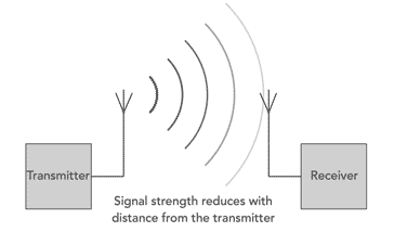
The free space propagation model is the simplest scenario for the propagation of radio signals. Here they are considered to travel outwards from the point where they are radiated by the antenna.
The way in which they propagate can be likened to the ripples of waves on a pond that travel outwards from the point where a stone is dropped into a pond.
As the ripples move outwards their level reduces until they finally disappear to the eye.
In the case of radio signal propagation, the waves spread out in three dimensions rather than the two dimensions of the pond example, but it is nevertheless a good way to explain the basics.
Free space path loss is a key element of many calculations. The concepts used in these calculations are applicable to many other calculations and as a result this is very useful.
Free space propagation signal level
It can be shown that the level of the signal falls as it moves away from the point where it has been radiated.
The rate at which it falls is proportional to the inverse of the square of the distance.
Where:
k = constant
d = distance from the transmitter
As a simple example this means that the signal level of a transmission will be a quarter of the strength at 2 metres distance that it is at 1 metre distance.
Where a radio signal comes under the influence of other factors, the basic formula can be altered to take account of this.
The exponent is altered to represent more accurately the real life scenario. In environments like the internals of buildings such as buildings, stadiums and other indoor environments, the path loss exponent can reach values in the range of 4 to 6.
Many mobile phone operators base their calculations on a terrestrial signal reduction around the inverse of the distance to the power 4. However tunnels can act as a form of waveguide and they can result in a path loss exponent values of less than 2.
Free space path loss calculation
It is possible to calculate the path loss between a transmitter and a receiver. The path loss proportional to the square of the distance between the transmitter and receiver as seen above and also to the square of the frequency in use.
The free space path loss can be expressed in terms of either the wavelength or the frequency. Both equations are given below:
In terms of wavelength
In terms of frequency
Where:
FSPL = Free space path loss
d = distance from the transmitter to the receiver (metres)
λ = signal wavelength (metres)
f = signal frequency (Hz)
c = speed of light (metres per second)
Free space loss formula frequency dependency
The free space loss equations above seem to indicate that the loss is frequency or wavelength dependent. In reality the attenuation resulting from the distance travelled in space is not frequency or wavelength dependent and is constant.
Looking at the free space path loss equations it is possible to see that the result is dependent upon two effects:
- The first results from the spreading out of the energy as the sphere over which the energy is spread increases in area. This is described by the inverse square law.
- The second effect results from the antenna aperture change and this is dependent upon physical size and the wavelength being used. This affects the way in which any antenna can pick up signals and it results in this element being frequency dependent.
Even though one element of the equation for free space path loss is non-frequency dependent, the other is and this results in the overall equation having a wavelength or frequency dependence.
Free space path loss equation in deciBels
It is normally more convenient to be able to express the path loss in terms of a direct loss in decibels. In this way it is possible to calculate elements including the expected signal, etc.
The equation below shows the path loss for a free space propagation application. It can also be used when calculating or estimating other paths as well.
Where: It is worth noting that the equation above does not include antenna gains and feeder losses. It is for two isotropic antennas, i.e. ones that radiate equally in all directions. It is possible to add the antenna gains into the equation
Where: The simple free space path loss calculator is given below. To use the free space path loss calculator, enter the figures as required and press calculate to provide the answer. As the IEEE "Standard Definitions of Terms for Antennas", IEEE 145-1983, states that a free space path loss is between two isotropic radiators. The calculator below is a path loss calculator because it includes the antenna gains. To make it a free space path loss calculator, antenna gains of 0 should be entered into both gain boxes. Using the path loss calculator, it should be remembered that the calculations have been scaled to accept distances in terms of kilometres and frequencies in terms of MHz. All antenna gains are expressed in decibels relative to an isotropic radiator and not a dipole which has a gain of 2.1 dB over an isotropic source. It should also be remembered that although the calculator is for path loss and is not strictly a free space path loss calculator, the calculation assumes there is free space between the two and no other effects affect the signal apart from the reduction due to signal distance and the antenna gains. A free space path loss calculation does not include the antenna gains and only looks at the path loss itself. Fro the equation and calculations for free space path loss, it would appear that it is inherently a poor decision to use higher frequencies. It poses the question whether there is an advantage to use lower frequencies. This is an interesting question, and whilst the mathematics would seem to suggest that this is the case, it is necessary to look a little more closely at what is happening to the signals. The frequency term in the equation results from the assumption of unity gain antennas at either end of the link. A larger antenna is required to obtain the same gain at a lower frequency, and as a result antennas at lower frequencies will be much larger. A larger antenna will collect energy from a larger area and therefore the loss between the ends of the link will be less even though the actual loss of the signal travelling is the same. Normally what happens with microwave and other very high frequency radio communications links is that the antennas for these higher frequencies can be made to have a higher gain within an acceptable space, and therefore the apparent higher losses at higher frequencies are not the issue that might be thought. Free space path loss calculations are an important element of any radio communications link or any signal level calculations for a radio based system. The calculations are easy to perform, but it must be remembered that there are very few places where a free space path is obtained. Only in outer space will these calculations become accurate. Even the upper reaches of the atmosphere will have an effect on a radio signal. Nevertheless the free space path loss calculations can form the basis of many calculations that are then adjusted to accommodate the real life aspects of the radio communications link. More Antenna & Propagation Topics:
d = distance of the receiver from the transmitter (km)
f = signal frequency (MHz)
Gtx = overall transmitter antenna gain including feeder losses
Grx = overall receiver antenna gain including feeder losses Free space path loss calculator
Is it bad to use high frequencies
EM waves
Radio propagation
Ionospheric propagation
Ground wave
Meteor scatter
Tropospheric propagation
Antenna basics
Cubical quad
Dipole
Discone
Ferrite rod
Log periodic antenna
Parabolic reflector antenna
Phased array antennas
Vertical antennas
Yagi
Antenna grounding
Installation guidelines
TV antennas
Coax cable
Waveguide
VSWR
Antenna baluns
MIMO
Return to Antennas & Propagation menu . . .


