
Photocouplers, Opto-couplers & Opto-isolators Explained
Understand exactly what photocouplers, optocouplers & optoisolators are and how they are used in electronic circuit designs to provide optical linking whilst providing electrical isolation.
Phototransistor Includes:
Phototransistor basics
Applications & circuits
Photodarlington
Optocoupler / optoisolator
Optocouplers can be described by a variety of different names including optoisolator, and photocoupler.
Essentially an optocoupler or photocoupler is a semiconductor device that uses a short optical path or link to couple a signal from one electrical circuit to another whilst providing electrical isolation.
The photocouplers or optocouplers are typically contained in a single package, often about the size of an integrated circuit, although there is a large degree of variation according to the intended application.
Photocouplers or optocouplers are used to provide many functions: they can be used to link data across two circuits, they can be used within optical encoders, where the optocoupler provides a means of detecting visible edge transitions on an encoder wheel to detect position, etc., and they can be used in many other circuits where optical links and transitions are needed.
They even form the essential element in solid state relays where an optical coupling is used to isolate the input and output electrically, whilst enabling the output to be switched according to the input state.. As a result, optical couplers or photocouplers are found in a surprisingly high number of circuits.
Photocoupler / Opto-coupler basics
The opto-coupler is a component that contains the two elements required for an opto-isolator:
- Light emitter: The light emitter is on the input side and takes the incoming signal and converts it into a light signal. Typically the light emitter is a light emitting diode.
- Light detector: The light detector within the opto-coupler or opto-isolator detects the light from the emitter and converts it back into an electrical signal. The light detector can be any one of a number of different types of device from a photodiode to a phototransistor, photodarlington, etc.
The light emitter and detector are tailored to match one another, having matching wavelengths so that the maximum coupling is achieved.
The opto-coupler may also contain other circuitry as well, For example it may include the series resistor for the LED or even the drive capability for the diode. The opto-coupler may also include an output amplifier.
Although an opto-coupler or opto-isolatoris usually thought of as a single integrated package, it is possible to achieve the same result using separate devices. However the mechanical arrangements need to be considered and this often makes an opto-coupler made from separate devices less convenient, although for opto-isolators there may be the need to utilise separate components for some applications.
Photocoupler / optocoupler terminology
The terms photocoupler, optocoupler and opto-isolator are often used interchangeably within electronics and technical literature when referring to components that undertake the same function.
Strictly, there are differences between the terms optoisolator and optocoupler. The distinguishing factor between the opto-coupler and opto-isolator is in the voltage difference expected between the input and output:
- Opto-coupler: The opto-coupler is generally thought of as being used to transmit analogue of digital information between circuits while maintaining electrical isolation at potentials up to 5 000 volts.
- Opto-isolator: The opto-isolator is generally used in power systems and used to transmit analogue or digital information between circuits where the potential difference is above 5 000 volts.
This is a rough guide to the differences between optocouplers and optoisolators. However the terms are still widely used interchangeably.
Opto-coupler symbol
The opto-coupler symbol used in circuit diagrams indicates the function and internal elements within the overall component. The symbol shows the LED, which is normally used as the light emitter.
The opto-coupler symbol also shows the receiver, often a phototransistor or photodarlington, although other devices including light sensitive diacs, etc may also be used. The relevant device type is shown within the optocoupler circuit symbol.

(phototransistor version)
Optocouplers can also be manufactured using other components. One format that is used in some AC power applications is an optocoupler based around a diac. This can be used for triggering a triac for mains switching or conduction angle control (i.e. dimming) applications.

Opto-coupler and opto-isolator packages
There is a variety of different packages used for both opto-couplers and opto-isolators.
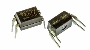
For the opto-couplers which are used for lower voltages, a variety packages are available. Often the opto-couplers come in small packages similar, but not always identical to the familiar Dual-In-Line (DIL) IC packages for conventional mount components.
SMD versions are also available, again in packages such as the Small Outline Integrated Circuit (SOIC) packages. These provide very compact options for containing the opto-couplers. However, ensure than any isolation requirements are met.
For opto-isolators operating at much higher voltages, different packages are available. Opto-isolators can be obtained in a wide variety of package styles including rectangles, cylinders, and specialty configurations. These package types are designed to provide higher isolation voltages than what can be achieved with DIL and SMD packages such as the SOIC.
Optocoupler and opto-isolator specifications
There are several parameters and specifications that need to be taken into account when using opto-couplers and opto-isolators:
Current transfer ratio, CTR: The current transfer ratio of an optocoupler is one of the key specifications. It is the ratio of the current that flows in the output device divided by the current on the input device.
The CTR will vary according to the type of opto-coupler used in the output, those using photodarlingtons will be much higher than those using ordinary phototransistors. Values may be anywhere between 10% and 2000% - 5000%.
It should be noted that the CTR tends to vary with the the input current level. Although it will vary according to the device, for man optocouplers it will peak for input current levels around 10mA falling either side of this value.
- Bandwidth: In order to understand the maximum data rates that can be used with an opto-coupler, it is necessary to know the bandwidth.
For many opto-couplers using phototransistors it may only be in the region of 250 kHz, and for those using photodarlingtons it may be a tenth of this figure. Some much faster optocouplers are available. Typically the lower the CTR, the faster the rise and fall times
- Input current: This is the current required for the input transmitter device - LED. The value is used to calculate the series resistor used to limit the current.
- Output device maximum voltage: For opto-couplers using transistors, the maximum figure will be equal to the VCE(max) for the transistor. For opto-couplers using other devices in the output, the equivalent rating should be used. Also remember that a suitable margin should be retained as it is never advisable to operate devices close tot heir maximum ratings.
Differences between optocouplers and solid state relays
There are many similarities between optocouplers / isolators etc and solid state relays.
Solid state relays are used in many areas as electronic switches to control AC or DC power.
The solid state relays use opto-coupling technology as the basis of their operation as they are required to provide high levels of resistance and isolation between the input and output circuits.
The main difference between optocouplers and solid state switches is that optocouplers and the like are normally used for low power applications. Solid state relays are used for much higher levels of power. Often the solid state relays are used to switch voltage levels up to hundreds of volts or more and current levels of up to tens of amps and more.
Typically optocouplers are contained within small IC packages either as surface mount devices or leaded semiconductor devices. However solid state relays are normally contained within much larger packages, often requiring to be bolted to a heat sink. They also often have screw contacts to provide the required current carrying capability.
In addition to this, solid state relays often contain additional circuitry - they are often a complete circuit block.
They may contain the drive circuitry for the LED in the opto-transmitter, and they may also contain surge and transient protection circuitry on the output. For AC applications, some solid state relays provide zero crossing switching for AC signals where the output device only switches when the AC waveform passes through the zero volt position. This reduces electromagnetic interference, EMI.
Photocouplers, optocouplers and opto-isolators are possibly more widely used than may be thought at first sight. They can be used in a variety of different ingenious ways providing optical links between circuits. This can be used to transfer data, provide electrical isolation between circuits, or to detect a break on the link. Whatever way they are used, they provide an invaluable function within many electronic circuits.
More Electronic Components:
Batteries
Capacitors
Connectors
Diodes
FET
Inductors
Memory types
Phototransistor
Quartz crystals
Relays
Resistors
RF connectors
Switches
Surface mount technology
Thyristor
Transformers
Transistor
Unijunction
Valves / Tubes
Return to Components menu . . .


