
SMD Resistors: Surface Mount Resistor
Surface mount resistors, SMD resistors use surface mount technology, SMT to provide considerable advantages in terms of space saving and automated manufacture of printed circuit boards.
Resistor Tutorial Includes:
Resistors overview
Carbon composition
Carbon film
Metal oxide film
Metal film
Wirewound
SMD resistor
MELF resistor
Variable resistors
Light dependent resistor
Thermistor
Varistor
Resistor colour codes
SMD resistor markings & codes
Resistor specifications
Where & how to buy resistors
Standard resistor values & E series
Surface mount resistors are used in vast quantities along with other surface mount electronic components. Most consumer and professional / industrial electronics is now manufactured using surface mount technology.
Using SMT improves manufacturing, enabling very high levels of automation and in addition to this the use of SMT improves reliability, enables greater levels of functionality to be achieved within a reasonable size and reduces costs significantly.
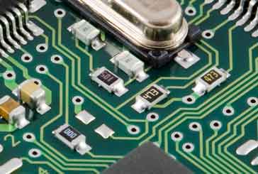
SMD resistors are the small components with figures on a dark background
The use surface mount technology enables the electronic components to be simply placed on the printed circuit board and then soldered in place by an automated process.
Accordingly surface mount resistors are the style of preference for virtually all electronics equipment in terms of the quantities used.
Surface mount resistors provide the same functionality as the more traditional axially leaded resistors although with a lower power dissipation capability and often lower stray inductance and capacitance, etc.
Surface mount resistors are available in all popular values, E3 to E192 as well as some specials if these are ever needed. Also that are available in a variety of sizes, some of which are now minute and difficult to handle manually.
Surface mount technology
SMD resistors are just one form of electronic component that uses surface mount technology. This form of component technology has now become commonplace for manufacturing electronic equipment as it enables much faster and more reliable construction of electronic printed circuit boards.
Surface mount components were first envisaged as a method for enabling automatic pick and place machines to be used more easily and reliably. Nowadays, the use of surface mount technology and in this case SMD resistors enable electronic circuit manufacture to be much faster and the finished product is much more reliable.
Surface mount technology enables the components to be placed onto the printed circuit board and then directly soldered to it. This eliminates the need for leads to connect the component body to the board and it also means that leads do not have to pass through the board which always presented significant issues for automated manufacture.

Note on the Surface Mount Technology:
Surface mount technology offers significant advantages for the mass production of electronic equipment. Traditionally components possessed leads at either end and these were attached to either terminals or later they were mounted through holes in a printed circuit board. Surface mount technology does away with the leads and replaces them with contacts that can be mounted directly onto the board enablong easy soldering.
Read more about Surface Mount Technology, SMT.
SMD resistor construction
SMT resistors or SMD resistors are rectangular in shape and as a result they are often known as chip resistors.
They have metallised areas at either end of the main ceramic body, and in this way they can be set onto a printed circuit board that has pads onto which the two ends are set to provide the connection.

The resistor is made by taking an alumina or ceramic substrate. The end connection electrode bases are then placed onto this and then this is fired to ensure they are robustly held in place.
Then a thin film of resistive material is deposited - this is typically metal oxide or a metal film - again the resistor is fired. The length, thickness and material used all determine the resistance of the component. However in many instances the resistive element will be trimmed using a YIG laser to obtain the required resistance.
Once the resistive element has been completed it is covered with successive layers of a protective coat which are all allowed to try between the applications. These layers of the protective coat not only prevent mechanical damage, but also prevent ingress of moisture and other contaminants.
The final stage is to apply a marking, if the resistor is sufficiently large for this.
Once the resistors have been completed they are packaged either in a form of blister roll for use on pick and place machines, or they can be supplied as loose components, which again can be used by pick and apace machines.
As the SMD resistors are manufactured using metal oxide or metal film and are protected using robust coating, this means that they are stable and have a good temperature and time tolerance.

The terminations at either end of the SMD resistor are key to the overall performance of the resistor. The internal connection between the resistor element and the terminations typically uses a nickel based layer and then the outer layer of the connection uses a tin based layer to provide good solderability a key requirement for these components.
SMD resistor packages
The SMD resistor packages generally conform to the standard SMD outlines for passive SMD components. Needless to say, occasionally other less standard packages may be used.
There is a growing trend in new designs to migrate towards some of the very small packages where power dissipation allows. This saves board space and allows further miniaturisation of the equipment, or to pack more functionality into the same space.
| Common Surface Mount Resistor Package Details | ||
|---|---|---|
| Package style | Size (mm) | Size (inches) |
| 2512 | 6.30 x 3.10 | 0.25 x 0.12 |
| 2010 | 5.00 x 2.60 | 0.20 x 0.10 |
| 1812 | 4.6 x 3.0 | 0.18 x 0.12 |
| 1210 | 3.20 x 2.60 | 0.12 x 0.10 |
| 1206 | 3.0 x 1.5 | 0.12 x 0.06 |
| 0805 | 2.0 x 1.3 | 0.08 x 0.05 |
| 0603 | 1.5 x 0.08 | 0.06 x 0.03 |
| 0402 | 1 x 0.5 | 0.04 x 0.02 |
| 0201 | 0.6 x 0.3 | 0.02 x 0.01 |
It can be seen that the package size descriptor is taken from he measurements of the resistor package measured in inches. An 0603 SMT resistor package measures 0.06 x 0.03 inches.
SMD resistor specifications
SMD resistors are manufactured by a number of different companies. Accordingly the specifications vary from one manufacturer to the next.
It is therefore necessary to look at the manufacturers rating for a specific SMD resistor before deciding upon exactly what is required. However it is possible to make some generalisations about the ratings that might be anticipated.
Power rating: The power rating needs careful consideration in any design. For designs using surface mount resistors, the levels of power that can be dissipated are smaller than those for circuits using wire ended components. As a guide typical power ratings for some of the more popular SMD resistor sizes are given below. These can only be taken as a guide because they may vary according to the manufacturer and exact type.
The power rating of a resistor is very dependent upon its size. Accordingly it is possible to generalise on the power ratings for SMD resistors of different sizes.
Typical SMD Resistor Power Ratings
Package style Typical Power Rating (W) 2512 0.50 (1/2) 2010 0.25 (1/4) 1210 0.25 (1/4) 1206 0.125 (1/8) 0805 0.1 (1/10) 0603 0.0625 (1/16) 0402 0.0625 - 0.031 (1/16 - 1/32) 0201 0.05 Some manufacturers will quote higher power levels than these. The figures given here are typical.
Like all electronic components, it is always advisable to de-rate the components and not run them close to their maximum ratings. It is often suggested that a maximum of 0.5 or 0.6 of the maximum rating is advisable. Derating below this will further improve the reliability.
- Temperature coefficient: Again the use of metal oxide film enables these SMD resistors to provide a good temperature coefficient. Values of 25, 50 and 100 ppm / °C are available. The technology used for SMT resistors is much better than some of the older technologies used for leaded resistors. Accordingly this provides much better temperature stability for the circuits.
- Tolerance: In view of the fact that SMD resistors are manufactured using metal oxide film they available in relative close tolerance values. Normally 5%, 2%, and 1% are widely available.
For specialist applications 0.5% and 0.1% values may be obtained. Even though close tolerance resistors may not be required, their use will help ensure better repeatability from one circuit or module to the next. It reduces the number of wide tolerance components used within the circuit. 2% resistors are widely used and cost little more than the 5% versions - their use may help in some instances. The use of 0.5% and 0.1% tolerance SMT resistors is not normally needed except for highly demanding requirements, and they are likely to cost much more than the 2% electronic components.
SMT resistors advantages & disadvantages
When considering the use of SMT resistors there advantages and limitations must be kept in mind. Even though SMT resistors are widely used there are a few points worth remembering:
SMT resistor advantages
- Size: Surface mount resistors are naturally much smaller than traditional axial or leaded components and therefore they enable greater levels of miniaturisation to be achieved.
- Reduced inductance: The size and construction of SMT resistors means that they have much lower levels of of stray inductance and capacitance and as a result they can be used for much higher frequency operation.
- Accuracy and tolerance: The technology used for SMT resistors means that they can be manufactured to high tolerances. They also possess a good temperature coefficient of resistance and long term resistance stability.
SMT resistor limitations
- Power rating: The power rating of SMT resistors is smaller than that of traditional axial leaded components. Although the current levels of most circuits using SMT components tends to be lower, care should be taken when designing circuits using hem to ensure that their power ratings are not exceeded.
Rework: Although surface mount technology gives a high level of reliability, there are occasions when rework is required. The technology is not always as robust as modules made using leaded components. That said if the proper techniques and tools are used, then it is properly achievable.
Often the biggest risk during re-work and repair is caused by leaving soldering iron on the pads for to long. This can give rise to damage month e board where pads can lift, and also within the resistor. Although he resistors are now more robust than they were years ago, caution should still be exercised.
SMT resistor markings
By their very nature SMT resistors are small - some of the sizes like 0201 are exceedingly small and in many cases there is no room for any meaningful markings. As the resistors are often loaded in reels onto a pick and place machine which automatically places the resistors and the reel is marked, there is often no need for them to be marked. Only when items are reworked is convenient to have them marked.

When the resistors are marked, figures are used rather than the colour codes used in leaded components. A number of different coding systems are used, but the most widely used utilises three numbers consisting of two significant figures and a multiplier.
MELF SMT resistors
Another form of surface mount resistor that can be used for some applications is known as a MELF resistor. The name comes from the words: Metal Electrode Leadless Face. They are used where very high reliability and performance are required. The resistors are cylindrical and therefore rather more difficult to handle. .
MELF surface mount resistors are not particularly widely used, but are sometimes seen for some specialist requirements where special electronic components are needed.
Surface mount resistors are manufactured in their billions and used in every electronic circuit using SMDs as they are very easy to assemble onto printed circuit boards. The SMD resistors are simple electronic components to manufacture now and can be obtained for a very low cost, especially when used in quantity. SMD resistors are now the most widely used form of resistor technology.
More Electronic Components:
Batteries
Capacitors
Connectors
Diodes
FET
Inductors
Memory types
Phototransistor
Quartz crystals
Relays
Resistors
RF connectors
Switches
Surface mount technology
Thyristor
Transformers
Transistor
Unijunction
Valves / Tubes
Return to Components menu . . .


