
Understanding Surface Mount Capacitors (SMD / SMT): all the key information
Understand SMD/SMT surface mount capacitors: construction, uses in electronic circuit designs, their performance, types available, sizes and all you need to know.
Capacitor Tutorial Includes:
Capacitor uses
Capacitor types
Electrolytic capacitor
Ceramic capacitor
Ceramic vs electrolytic
Tantalum capacitor
Film capacitors
Silver mica capacitor
Super capacitor
Surface mount capacitors
Specifications & parameters
How to buy capacitors - hints & tips
Capacitor codes & markings
Conversion table
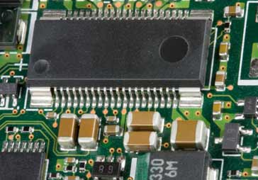
SMD or SMT surface mount capacitors are used in high volume manufacture - quantities used are numbered in the billions. They are small, leadless and can be placed onto modern printed circuit boards using pick and place machines used in modern manufacturing.
There are many different types of SMD capacitor ranging from ceramic types, through tantalum varieties to electrolytics and more. Of these, the ceramic SMD capacitors are the most widely used.
Separate pages have been devoted to the different dielectric technologies, but this page provides a summary of the specific surface mount capacitor details.
Surface mount technology
SMD capacitors are just one form of component that uses surface mount technology. This form of component technology has now become commonplace for manufacturing electronic equipment as it enables much faster and more reliable construction of electronic printed circuit boards.
Note on the Surface Mount Technology:
Surface mount technology offers significant advantages for the mass production of electronic equipment. Traditionally components possessed leads at either end and these were attached to either terminals or later they were mounted through holes in a printed circuit board. Surface mount technology does away with the leads and replaces them with contacts that can be mounted directly onto the board enablong easy soldering.
Read more about Surface Mount Technology, SMT.
SMD capacitor basics
Surface mount capacitors are basically the same as their leaded predecessors. However instead of having leads they have metallised connections at either end.
This has a number of advantages:
- Ease of use in manufacturing: As with all other surface mount components, SMD capacitors are very much easier to place using automated assembly equipment.
- Size: SMD capacitors can be made very much smaller than their leaded relations. The fact that no wired leads are required means that different construction techniques can be sued and this allows for much smaller components to be made.
- Lower spurious inductance: The fact that no leads are required and components are smaller, means that the levels of spurious inductance are much smaller and these capacitors are much nearer the ideal component that their leaded relations.
- Lower cost: Not only can these components be used more easily in production reducing the production costs of the final product, but they also lend themselves more easily to their own high volume manufacture. The lack of leads makes their manufacture easier. In addition to this, the enormous volumes in which they are manufactured has resulted in significant cost reductions in their production.
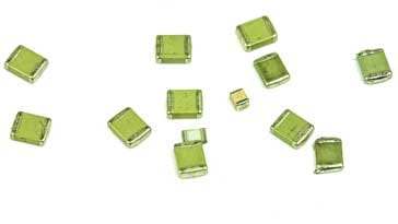
Multilayer ceramic SMD capacitors
The multilayer ceramic SMD capacitors form the majority of SMD capacitors that are used and manufactured. They are normally contained in the same type of packages used for resistors.
| Multilayer Ceramic SMD Capacitors Dimensions | ||
|---|---|---|
| Size designation | Measurements (mm) | Measurements (inches) |
| 1812 | 4.6 x 3.0 | 0.18 x 0.12 |
| 1206 | 3.0 x 1.5 | 0.12 x 0.06 |
| 0805 | 2.0 x 1.3 | 0.08 x 0.05 |
| 0603 | 1.5 x 0.8 | 0.06 x 0.03 |
| 0402 | 1.0 x 0.5 | 0.04 x 0.02 |
| 0201 | 0.6 x 0.3 | 0.02 x 0.01 |
Construction: The multilayer ceramic SMD capacitor consists of a rectangular block of ceramic dielectric in which a number of interleaved precious metal electrodes are contained. This multilayer structure gives rise to the name and the MLCC abbreviation, i.e. Multi-Layer Ceramic Capacitor.
This structure gives rise to a high capacitance per unit volume. The inner electrodes are connected to the two terminations, either by silver palladium (AgPd) alloy in the ratio 65 : 35, or silver dipped with a barrier layer of plated nickel and finally covered with a layer of plated tin (NiSn).
Ceramic capacitor manufacture: The raw materials for the dielectric are finely milled and carefully mixed. Then they are heated to temperatures between 1100 and 1300°C to achieve the required chemical composition. The resultant mass is reground and additional materials added to provide the required electric properties.
The next stage in the process is to mix the finely ground material with a solvent and binding additive. This enables thin sheets to be made by casting or rolling.
For multilayer capacitors electrode material is printed on the sheets and after stacking and pressing of the sheets co-fired with the ceramic compact at temperatures between 1000 and 1400°C. The totally enclosed electrodes of a multilayer capacitor ceramic capacitor, MLCC guarantee good life test behaviour as well.
SMD electrolytic capacitors
Electrolytic capacitors are now being used increasingly in SMD designs. Their very high levels of capacitance combined with their low cost make them particularly useful in many areas.
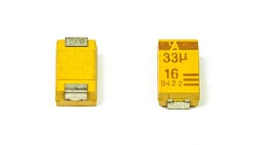
Often SMD electrolytic capacitors are marked with the value and working voltage. There are two basic methods used.
One is to include their value in microfarads, µF, and another is to use a code. Using the first method a marking of 33 6V would indicate a 33 µF capacitor with a working voltage of 6 volts.
An alternative code system employs a letter followed by three figures. The letter indicates the working voltage as defined in the table below and the three figures indicate the capacitance on pico-farads.
As with many other marking systems the first two figures give the significant figures and the third, the multiplier. In this case a marking of G106 would indicate a working voltage of 4 volts and a capacitance of 10 times 10^6 pico-farads. This works out to be 10µF.
| Electrolytic SMD Capacitor Codes | |
|---|---|
| Letter Code | Voltage |
| e | 2.5 |
| G | 4 |
| J | 6.3 |
| A | 10 |
| C | 16 |
| D | 20 |
| E | 25 |
| V | 35 |
| H | 50 |
SMD tantalum capacitors
Tantalum SMD capacitors are widely used to provide levels of capacitance that are higher than those that can be achieved when using ceramic capacitors. As a result of the different construction and requirements for SMD tantalum capacitors, there are some different packages that are used for them. These conform to EIA specifications.
| Tantalum SMD Capacitors Dimensions | ||
|---|---|---|
| Size designation | Measurements (mm) | EIA Designation |
| Size A | 3.2 x 1.6 x 1.6 | EIA 3216-18 |
| Size B | 3.5 x 2.8 x 1.9 | EIA 3528-21 |
| Size C | 6.0 x 3.2 x 2.2 | EIA 6032-28 |
| Size D | 7.3 x 4.3 x 2.4 | EIA 7343-31 |
| Size E | 7.3 x 4.3 x 4.1 | EIA 7343-43 |
SMD tantalum capacitors were for many years the only type of high value SMD capacitor available. It took some years before SMD electrolytic capacitors were developed, because of the requirement for SMD capacitors to be able to withstand the high soldering temperatures, and as a result, tantalums were widely used. Nowadays, SMD electrolytic capacitors are the main type used, although tantalums are still used in large quantities as their performance tends to be better in some respects.
SMD capacitor codes
Comparatively few SMD capacitors have their values marked on their cases. This means that great care must be taken when handling them to ensure they are not misplaced or mixed. However a few capacitors do have markings. The capacitor values are coded. This means that it is necessary to know the SMD capacitor codes. These are simple and easy to decode.
A three figure SMT capacitor code is normally used as there is usually little space for anything more. In common with other marking codes the first two indicate the significant figures, and the third is a multiplier.
Advantages & disadvantages of SMD capacitors
As with any technology there are advantages and disadvantages to the use of a particular technology and the same is true for SMD capacitors.
Advantages of SMT capacitors
- Small
- Low cost
- Easy placement using modern pick and place machines in manufacture
- High performance
Disadvantages of SMT capacitors
- Small size can mean some are susceptible to ESD
- Small size makes them difficult to handle manually
- Can be damaged more easily if taken outside their working limits - often les margin than with a larger leaded device
Surface mount capacitors are used in their billions within facilities that mass produce electronics equipment. Their size and the ability to be placed onto a printed circuit board enable them to be used with ease. As a result, surface mount capacitors are used in virtually all positions on mass produced electronic equipment.
More Electronic Components:
Batteries
Capacitors
Connectors
Diodes
FET
Inductors
Memory types
Phototransistor
Quartz crystals
Relays
Resistors
RF connectors
Switches
Surface mount technology
Thyristor
Transformers
Transistor
Unijunction
Valves / Tubes
Return to Components menu . . .


