
Op Amp Active Notch Filter Circuit
Op amp circuit for an active notch filter can be used to remove single frequencies or small bands of frequencies and the electronic circuit design is easy.
Op-amp Circuits Include:
Introduction
Circuits summary
Inverting amplifier
Summing amplifier
Non-inverting amplifier
Inverting vs non-inverting circuits
Variable gain amplifier
High pass active filter
Low pass active filter
Bandpass filter
Notch filter
Comparator
Schmitt trigger
Multivibrator
Bistable
Integrator
Differentiator
Wien bridge oscillator
Phase shift oscillator
Operational amplifiers provide an excellent way of making and designing notch filters. Op amp circuits for active notch filters are very effective whilst being easy to design and construct using a minimal number of electronic components.
Notch filters can be used in a number of different applications where a particular frequency or band of frequencies needs to be removed. Often notch filers are fixed frequency, although it is possible to design some that have variable frequencies.
Fixed frequency notch filters find applications such as removing fixed frequency interference like mains hum, from audio circuits. They can also be used in electronic circuit design in many areas, conveniently removing a single frequency or narrow band of frequencies.
Notch filter response
As the name notch filter implies it provides a notch or narrow band over which the filter removes the signals on that frequency.
The ideal response for any notch filter would be a completely flat response over the usable range with the exception of the notch frequency. Here it would fall very fast providing a high level of attenuation that is able to remove the unwanted signal.
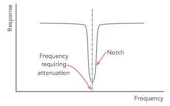
In reality, perfection is not achievable, but when using an op amp circuit, the high levels of gain of the operational amplifier itself mean that high levels of attenuation and narrow notches can be achieved very easily with a minimum number of electronic components in addition to the operational amplifier.
Op amp active notch filter circuit
The diagram below shows an op amp circuit for an active notch filter using a single operational amplifier and a few additional electronic components.
The notch filter circuit is quite straightforward and the electronic circuit design calculations for the component values are also easy to determine.

The active notch filter circuit is quite straightforward to design. It employs both negative and positive feedback around the operational amplifier chip and in this way it is able to provide a high degree of performance.
Calculation of the value for the circuit is very straightforward. The formula to calculate the resistor and capacitor values for the notch filter circuit is:
Where:
fnotch = centre frequency of the notch in Hertz
Π = 3.142
R and C are the values of the resistors and capacitors in Ω and Farads
Notch filter design precautions
When building the active notch filter circuit, high tolerance components must be used to obtain the best performance. Typically they should be 1% or better. A notch depth of 45 dB can be obtained using 1% components, although in theory it is possible for the notch to be of the order of 60 dB using ideal components. R1 and R2 should be matched to within 0.5% or they may be trimmed using parallel resistors.
A further item to ensure the optimum operation of the circuit is to ensure that the source impedance is less than about 100 ohms. Additionally the load impedance should be greater than about 2 M Ohms.
The circuit is often used to remove unwanted hum from circuits. Values for a 50 Hz notch would be: capacitors: C1, C2 = 47 nF, resistors: R1, R2 = 10 k, R3, R4 = 68 k.
Op amp twin T notch filter circuit with variable Q
Although the fixed notch filter circuit can be used in many electronic circuit designs, sometimes a variable notch width of Q may be required. This can also be provided using a simple op amp circuit.
A twin T notch filter with variable Q is simple to realise and it can provide a good level of rejection at the notch frequency. This op amp circuit uses two operational amplifiers, and the twin "T" section can be seen between the two operational amplifiers.
The variable Q function for the twin T active notch filter is provided by the potentiometer placed on the non-inverting input of the lower operational amplifier in the diagram.

Calculation of the value for the circuit is very straightforward. The formula is the same as that used for the passive version of the twin T notch filter.
Where:
fnotch = cut off frequency in Hertz
π = 3.142
R and C are the values of the resistors and capacitors as in the circuit
The value for the potentiometer is not at all critical. It should not be so high that the resistance is loaded by the input impedance of the second operational amplifier. As it is also seen as a resistor load by the first operational amplifier, it should not be so low that it presents a significant load. This resistor only acts as a potential divider to present the required proportion of the output to the input of the second operational amplifier.
The potentiometer could be anywhere between about 4.7kΩ and 47kΩ. As standard operational amplifiers have an input resistance of around 250kΩ there is sufficient margin for the 47kΩ potentiometer.
The op amp circuit for a notch filter can be very useful, and the adjustment facility for the Q can also be very handy. It uses comparatively few electronic components: just two operational amplifiers, which could be incorporated into a single integrated circuit package as well as three resistors, three capacitors and the potentiometer to adjust the value of Q.
The main drawback of the notch filter circuit is that as the level of Q is increased, the depth of the null reduces. Despite this, the op amp circuit can be successfully used in many electronic circuit designs for a variety of applications.
Electronic components for notch filter designs
The choice of the electronic components used in an active filter is key to the successful operation of the circuit. For an active notch filter, the tolerance and performance of the electronic components is key.
Changes in the electronic component values as a result of their tolerance can significantly alter alter the the notch and its depth. All components in the notch determining area of the circuit should be of a tight tolerance, 1% or better.
Today metal film resistors are available in leaded and surface mount device format. These resistors are not only low noise, but they also can be bought in close tolerance forms. Typically they are available as 1%, 2% or occasionally 5% versions. As there is often little cost difference, the use of 1% resistors is a good choice.
In terms of the capacitors, electrolytic capacitors are to be avoided at all costs. Not only are they polarised but their tolerance is very poor. Typically electrolytic capacitors have a tolerance of -20% and +80%, so they are not at all accurate. Tantalum electrolytic capacitors are also to be avoided. They are better than electrolytic capacitors, but they are also polarised and do not provide a sufficient level of accuracy.
Ceramic capacitors offer a good level of performance and they are normally available in the ranges required. They are also available as both leaded and surface mount devices. Dependent upon the actual dielectric, very high tolerance capacitors are available, and the right types will offer good performance.
Plastic film capacitors are another good choice as many types offer good tolerance levels. However film capacitors are generally only available as leaded devices and not as surface mount devices.
The two op amp active notch filter circuits are very easy to design and use. Their performance is good enough for most applications, but if they need to be cascaded, then care must be taken to ensure they are on exactly the same frequency by using very close tolerance components for the frequency determining elements.
More Circuits & Circuit Design:
Op Amp basics
Op Amp circuits
Power supply circuits
Transistor design
Transistor Darlington
Transistor circuits
FET circuits
Circuit symbols
Return to Circuit Design menu . . .


