
Basic Cellular Communications System Concepts
The concept of a cellular structure which enables frequency re-use of frequencies without undue levels of interference is at the core of modern mobile communications systems.
Cellular / Mobile Telecommunications Basics Includes:
What is cellular communications
Concept of cellular system
Radio access network, RAN
Basestation Technology
Base station antenna technology
Multiple access techniques
Duplex techniques
What's inside a cellphone
SIM cards
Handover
Backhaul
The concept of a cellular type of structure to plan the frequency coverage of different mobile communications to provide frequency re-use whilst minimising the levels of interference was at the centre of mobile communications when it was first launched and it still is today.
Cellular systems are widely used today and cellular technology need to offer very efficient use of the available frequency spectrum.
With billions of mobile phones in use around the globe today and very high levels of usage in centres of population, it is necessary to re-use the available frequencies many times over without mutual interference from one base station to the next.
It is this concept of frequency re-use that is at the very heart of mobile communications or cellular telecommunications technology.
However the infrastructure technology needed to support it is not simple, and it requires a significant investment to introduce and maintain any network as vast numbers of base stations are required to give good coverage.
The need for a spectrum efficient system
To illustrate the need for efficient spectrum usage for a radio communications system, take the example where each user is allocated a channel.
While more effective systems are now in use, the example will take the case of an analogue system. Each channel needs to have a bandwidth of around 25 kHz to enable sufficient audio quality to be carried as well as enabling there to be a guard band between adjacent signals to ensure there are no undue levels of interference.
Using this concept it is only possible to accommodate 40 users in a frequency band 1 MHz wide. Even of 100 MHz were allocated to the system this would only enable 4000 users to have access to the system.
Today cellular systems have millions of subscribers and therefore a far more efficient method of using the available spectrum is needed.
Cell system for frequency re-use
The method that is employed is to enable the frequencies to be re-used. Any radio transmitter will only have a certain coverage area.
Beyond this the signal level will fall to a limited below which it cannot be used and will not cause significant interference to users associated with a different radio transmitter. This means that it is possible to re-use a channel once outside the range of the radio transmitter.
The same is also true in the reverse direction for the receiver, where it will only be able to receive signals over a given range. In this way it is possible to arrange split up an area into several smaller regions, each covered by a different transmitter / receiver station.
These regions are conveniently known as cells, and give rise to the name of a "cellular" technology used today. Diagrammatically these cells are often shown as hexagonal shapes that conveniently fit together.

In reality this is not the case. They have irregular boundaries because of the terrain over which they travel. Hills, buildings and other objects all cause the signal to be attenuated and diminish differently in each direction.
It is also very difficult to define the exact edge of a cell. The signal strength gradually reduces and towards the edge of the cell performance will fall. As the mobiles themselves will have different levels of sensitivity, this adds a further greying of the edge of the cell. Therefore it is never possible to have a sharp cut-off between cells. In some areas they may overlap, whereas in others there will be a "hole" in coverage.
Cell clusters
When devising the infrastructure technology of a cellular system, the interference between adjacent channels is reduced by allocating different frequency bands or channels to adjacent cells so that their coverage can overlap slightly without causing interference. In this way cells can be grouped together in what is termed a cluster.
Often these clusters contain seven cells, but other configurations are also possible. Seven is a convenient number, but there are a number of conflicting requirements that need to be balanced when choosing the number of cells in a cluster for a cellular system:
- Limiting interference levels
- Number of channels that can be allocated to each cell site
It is necessary to limit the interference between cells having the same frequency. The topology of the cell configuration has a large impact on this. The larger the number of cells in the cluster, the greater the distance between cells sharing the same frequencies.
In the ideal world it might be good to choose a large number of cells to be in each cluster. Unfortunately there are only a limited number of channels available. This means that the larger the number of cells in a cluster, the smaller the number available to each cell, and this reduces the capacity.
This means that there is a balance that needs to be made between the number of cells in a cluster, and the interference levels, and the capacity that is required.
A typical seven cell cluster. It is worth noting that although a hexagon is shown in this idealised diagram, the actual cell boundaries will be very irregular and will depend on the terrain and other factors.
Cell size
Even though the number of cells in a cluster in a cellular system can help govern the number of users that can be accommodated, by making all the cells smaller it is possible to increase the overall capacity of the cellular system.
However a greater number of transmitter receiver or base stations are required if cells are made smaller and this increases the cost to the operator. Accordingly in areas where there are more users, small low power base stations are installed.
The different types of cells are given different names according to their size and function:
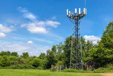
Macro cells: Macro cells are large cells that are usually used for remote or sparsely populated areas. These may be 10 km or possibly more in diameter.
For these types of cells, tall towers are generally needed and the height will not only depend upon the coverage required, but also what the local planning regulations might allow as some countries do not allow mobile communications towers above a certain height, etc.
Micro cells: Micro cells are those that are normally found in densely populated areas which may have a diameter of around 1 km.
Having a small diameter, the signals will not extend so far and this will enable the frequencies or channels to be re-used within a relatively short distance. Having smaller cells sizes enables higher frequency re-use and much higher density of users to be supported.
Pico cells: Picocells are generally used for covering very small areas such as particular areas of buildings, or possibly tunnels where coverage from a larger cell in the cellular system is not possible.
Obviously for the small cells, the power levels used by the base stations are much lower and the antennas are not position to cover wide areas. In this way the coverage is minimised and the interference to adjacent cells is reduced.
Selective cells: Sometimes cells termed selective cells may be used where full 360 degree coverage is not required. They may be used to fill in a hole in the coverage in the cellular system, or to address a problem such as the entrance to a tunnel etc.
Umbrella cells: Another type of cells known as an umbrella cell is sometimes used in instances such as those where a heavily used road crosses an area where there are microcells. Under normal circumstances this would result in a large number of handovers as people driving along the road would quickly cross the microcells.
An umbrella cell would take in the coverage of the microcells (but use different channels to those allocated to the microcells). However it would enable those people moving along the road to be handled by the umbrella cell and experience fewer handovers than if they had to pass from one microcell to the next.
Sectorisation
With the number of subscribers increasing, it was soon found that the traditional concept of a base station in the centre of the cell with an omnidirectional antenna (in the horizontal plane) was not the optimum way forwards.
Instead, base stations migrated to an antenna system that had tree, or possibly more antennas with half power beam-widths of, say 65, 90 or 120 degrees. in the horizontal plane.
There were two basic ways of looking at cells with this approach, although in reality the final outcome was similar.
In the US the cells used a layout that was based upon a hexagonal cellular layout wit the base staton at the centre of the cell.
By adding directional antennas so that, say, 120° was illuminated by each antenna, three sectors were created within the cell. This enabled better coverage to be obtained, and also it gave a much higher capacity. The antenna coverage is such that it needs to illuminate a coverage area which is the shape of a rhombus.
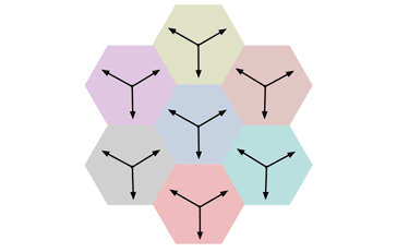
Outside the USA, a similar style of approach was used, but it was implemented in a different way.
Again , directional antennas were used, but instead of locating them at the centre of the cell, they were placed at the intersections of the three hexagons. In this case the antenna should cover a hexagonal shape rather than a rhombus.

Although the two solutions look very similar, there is a subtle but important difference between them.
In the system used within the USA where the antennas are directed between the closest neighbouring base stations, whereas for the second option, the antennas are directed towards the nearest base station. This may not be an issue if they are operating on different channels.
Both of these systems have their own advantages and disadvantages.
Modern single frequency networks
Modern cellular systems use modulation formats that are able to accommodate interference from other cells and therefore the concept of frequency re-use is rather different these days.
The original 3G systems used a modulation scheme called CDMA, code division multiple access, and this meant that a number of different users would all use the same frequency, but with different codes to differentiate them. It has been likened to people in a noising room all speaking different languages, and even though noise levels are high, it is stil possible to understand the language you are listening to.
This meant that adjacent cells could even operate on the same frequency, although interference at the cell boundaries where two or more cells were being received added interference when signals were already weak.
The 4G and 5G systems use a modulation scheme called OFMDMA, orthogonal frequency division multiple access, and again large numbers of users are able to access what is effectively the same carrier.
However to prevent interference levels rising too high when signals from different cells are of around the same strength, especially on the cell boundaries, some use of different frequencies provides improvements.
These developments mean that having adjoining cells on a different frequency is les of an issue and this considerably opens up the amount of spectrum that can be used.
Network planning
Planning a network is a very complicated topic. It is necessary to provide the right level of coverage and also enable sufficient frequency re-use to provide all the users with a good level of service.
Although more frequencies are being allocated to mobile communications, the number of users is rising, and also the bandwidth each user needs is rising as they expect to be able to download video and transfer other files at increasing speeds. All this demands more frequency spectrum.
In view of the increasing needs for a high level of service, the network planning needs to be optimised so that the maximum amount of frequency re-use can be gained whilst still taking in the needs of users - if they are walking slowly along a high street they will move from one base station coverage area to another as a user travelling along a motorway. If too many handovers are undertaken, this takes up the network resources as well as having the possibility of dropping a call.
Accordingly it makes sense to have larger cell sizes, possibly with more channels along a motorway, possibly using selective cells to cover the motorway itself. This will enable the users travelling along the motorway to get good coverage and sufficient resource.
For those travelling less swiftly, it is possible to use smaller cell sizes to give better frequency re-use and enable sufficient bandwidth levels to be provided.
Planning the network to provide good coverage, few dead zones and and sufficient bandwidth means that many factors need to be balanced to provide the high level of service we are able to receive today.
Often mobile communications providers will undertake drive tests where they drive round an area to check the performance and coverage.
They also have advanced monitoring software which will show where the issues are occurring and provide many insights into the network performance.
Although the illustrations used here to describe the basic infrastructure technology used for cellular systems refers to the original first generation systems, it serves to provide an overview of the basic cellular concepts that form the cornerstones of today's cellular technology. New techniques are being used, but the basic concepts employed are still in in use.
Wireless & Wired Connectivity Topics:
Mobile Communications basics
2G GSM
3G UMTS
4G LTE
5G
Wi-Fi
Bluetooth
IEEE 802.15.4
DECT cordless phones
Networking fundamentals
What is the Cloud
Ethernet
Serial data
USB
LoRa
VoIP
SDN
NFV
SD-WAN
Return to Wireless & Wired Connectivity

