
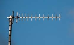
Yagi Antenna / Yagi-Uda Aerial
The Yagi antenna or aerial sometimes called the Yagi-Uda antenna is widely used for broadcast, domestic and commercial radio communications applications where gain and directivity are required from an RF antenna design.
Yagi antenna includes:
Yagi antenna
Yagi antenna theory & calculations
Yagi antenna gain & directivity
Yagi feed impedance & matching
The Yagi antenna or Yagi-Uda antenna or aerial is a particularly popular where directivity and gain are required for an antenna installation.
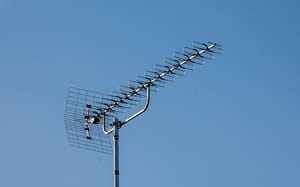
Although the Yagi directive antenna has become particularly popular for television reception, it is also used in many other applications, both domestic and commercial or professional reception and two way radio communications.
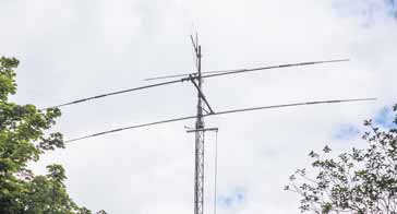
The antenna is well established and although it is more complicated than some other types, the basic construction is straightforward and it can provide a robust antenna installation.
The main attributes of the Yagi antenna are its gain and directivity. These enable it to provide improved reception by enabling better levels of signal to be received, and by reducing interference levels by only picking up signals from a given direction.
For transmitting much better use of the available power is made because it is possible to focus the transmitted power toward the region where it is needed. Similarly levels of general interference can be reduced to other users because the signal is not transmitted to areas where it is not needed.
In view of all the benefits provided by the Yagi directional antenna, the additional cost of manufacturing resulting from the extra hardware required over some other types of antenna is well worth the investment for many radio communications and reception antenna installations.
Yagi antenna development
Although the Yagi antenna is now widely used, it was only in the late 1920s and early 1930s when it started to be used.
Although the name, Yagi is normally used, its full name is the Yagi-Uda antenna. The name is derived from its two Japanese inventors Hidetsugu Yagi and Shintaro Uda.
The RF antenna design concept was first outlined in a paper that Yagi presented in 1928. Since then its use has grown rapidly to the stage where today a television antenna is synonymous with an RF antenna having a central boom with lots of elements attached.
The design for the Yagi antenna appears to have been initially developed not by Yagi who was a student, but his Professor Shintaro Uda. However all the original papers were all in Japanese and accordingly the design was not publicised outside Japan.
Uda did not speak English, but his student did. Accordingly it was Hidetsugu Yagi who wrote papers in English. As a result the design is often incorrectly only attributed to Yagi.
It is apparent that Yagi did not aim to steal the publicity at all and as a result the proper name for the antenna design now bears the names of both men and is formally known as the Yagi-Uda antenna.
Yagi antenna - the basics
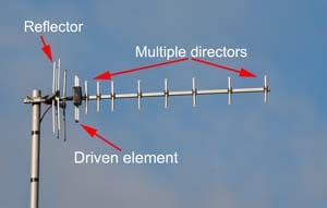
The Yagi directive antenna design has a dipole as the main radiating or driven element to which power is applied directly from a feeder.
Further 'parasitic' elements are added which are not directly connected to the driven element but pick up power from the driven dipole element and re-radiate it.
The key to the operation of this directive antenna is that the phase of the power radiated by the additional elements is different to that of the phase of the power from the driven element.
The phase is in such a manner that it affects the properties of the whole Yagi antenna as a whole, causing power to be focussed in one particular direction and removed from others.
The directions in which the power that is re-radiated by the parasitic elements is on phase have the signal reinforced, whereas in the directions where it is out of phase the signals cancel out and the signal in that direction is reduced.
The amplitude and phase of the current that is induced in the parasitic elements is dependent upon their length and the spacing between them and the dipole or driven element.

If an element is longer than the resonant length, i.e. that of the driven element, then it becomes inductive, and shorter it becomes capacitive. In this way the phase of the currents in elements that are shorter or longer are different.
Using a knowledge of this fact, it is possible to create three different types of element that have different effects on the overall radiation pattern of the antenna.
There are three types of element within a Yagi antenna:
Driven element: The driven element is the Yagi antenna element to which power is applied. It is normally a half wave dipole or often a folded dipole.
A folded dipole element is often used because the proximity of the other parasitic elements causes the feed impedance of the dipole to fall. Using a folded dipole brings the feed impedance back to a value that provides a better match to the feeder used.
Often coaxial cable is used to feed the antenna. Coax is an unbalanced feeder whereas the dipole is a balanced antenna. Accordingly an element referred to as a balun (effectively a transformer) should be used to ensure that the dipole is driven correctly.
Reflector: The reflector element is made to be about 5% longer than the driven element. The Yagi antenna will generally only have one reflector because additional reflectors make virtually no difference.
The reflector is placed behind the main driven element, i.e. the side away from the direction of maximum sensitivity.
Many designs use reflectors consisting of a reflecting plate, or a series of parallel rods simulating a reflecting plate. This gives a slight improvement in performance, reducing the level of radiation or pick-up from behind the antenna, i.e. in the backwards direction. This can help in reducing the levels of interference received.
Typically a reflector will add around 4 or 5 dB of gain in the forward direction.
Director: The director or directors are made to be shorter than the driven element. There may be none, one of more reflectors in the Yagi antenna. The director or directors are placed in front of the driven element, i.e. in the direction of maximum sensitivity.
Typically each director will add around 1 dB of gain in the forward direction, although this level reduces as the number of directors increases.
The Yagi antenna exhibits a directional pattern consisting of a main forward lobe and a number of spurious lobes to the rear and the side.
The main spurious lobe is the reverse one caused by radiation in the direction of the reflector.

The antenna can be optimised to either reduce radiation in the reverse direction by altering the length and spacing of the reflector or it can be optimised to produce the maximum level of forward gain. Unfortunately the two conditions do not coincide exactly and a compromise on the performance has to be made depending upon the application. It is necessary to choose either maximum front to back ratio or maximum forward gain.
Yagi antenna advantages
The Yagi antenna offers many advantages over other types of antenna in many applications, yet both advantages and disadvantages need to be weighed up to ensure the correct type of antenna is chosen for any particular use.:
- Directivity: The Yagi antenna is directional enabling interference levels to be minimised for receiving and transmitting.
- Gain: The Yagi antenna has gain allowing lower strength signals to be received.
- Straightforward construction: The Yagi antenna is mechanically relatively straightforward when compared to other designs. It can be constructed using straight rods which are simple to use and robust for most instances.
- Polarisation: The construction enables the antenna to be mounted easily on vertical and other poles with standard mechanical fixings
The Yagi antenna also has a number of disadvantages that also need to be considered.
- Max gain ~20dB Gain is limited to around 20dB or so for a single antenna otherwise it becomes too large and beamwidth narrows. For low frequency antennas the physical size means that the maximum number of elements and hence the gain is much lower than 20dB.
- Long for high gain: For high gain levels the antenna becomes very long.
Yagi antenna specifications
There are many different specifications that are important when selecting a Yagi for an antenna installation. Some of the parameters affect the radio performance, and others are equally important but refer to the mechanical aspects..
Although, possibly the forward gain is one of the headline specifications, there are several others of importance.
Antenna gain: The gain of the Yagi antenna is probably the headline specification that many people will look for first of all. There are two main figures: one is the gain over a dipole, dBd, and the second is the gain over an isotropic source, dBi. The gain over an isotropic source will be 2.1 dB higher than that over a dipole.
Front to back ratio: The front to back ratio specification is the ratio of the signal in the forward (wanted) direction to the signal in the reverse direction. This specification is important where it is either necessary to prevent signal being transmitted in the reverse direction, possibly to reduce interference, or where it is necessary to reduce the level of reception off the back of the beam. This can be particularly important if there could be levels of interfering signals that might need to be reduced in strength.
The actual front to back ratio will vary according to the antenna, but it may be anywhere up to 20dB for a larger antenna.
Beamwidth: The beamwidth specification for the Yagi gives a measure of the width of the beam. The more gain an antenna has, then the narrower its beamwidth will be. In turn this affects the accuracy to which the antenna needs to be orientated towards the source of the signal. As it can sometimes be difficult to accurately orientate an antenna, having a lot of gain and a very narrow beam width can make it more difficult to set up.
The beamwidth is often measured as the half power beamwidth, i.e. the angle between the points where the radiation level falls to half, i.e. to the -3dB point. This angle is measured in degrees and normally given in both the horizontal and vertical axes.
Frequency and bandwidth: Yagi antennas are frequency dependent. Not only do they have a centre operating frequency, but they also have a bandwidth over which they will operate satisfactorily. Often the bandwidth is limited either by the impedance match and hence the VSWR, and the other is the bandwidth over which they will operate to give a satisfactory directional pattern.
Weight: The weight of the antenna can be an issue for some antenna installations. The brackets need to be sufficiently robust to hold the antenna, so if the antenna is large, then much stronger brackets are required.
Length: The length of the antenna may be an issue for some antenna installations. The more gain the antenna has, the longer it will be. This may impact the mountings required for the overall installation - the longer the antenna is the greater the effect of the wind will be on it.
When considering buying or installing a Yagi antenna, it is necessary to understand the specifications and also balance the various figures against one another to obtain the best overall compromise of performance, cost, size and the like.
The most successful antenna installation may not alway be the one that just has the highest gain, but one that operates reliably and is also able to reduce the levels of interference from other directions, an antenna installation that can be set up suitably to provide the optimum performance , etc.
The Yagi antenna is a very practical form of RF antenna design that is suited for applications where gain and directivity are needed. Although the cost is higher than more basic antennas, the Yagi often provides the most cost effective option for gain, directivity and overall performance. For frequencies at VHF and above, the size of the Yagi is very acceptable and it has become the standard type of antenna used where directionality and gain are needed.
More Antenna & Propagation Topics:
EM waves
Radio propagation
Ionospheric propagation
Ground wave
Meteor scatter
Tropospheric propagation
Antenna basics
Cubical quad
Dipole
Discone
Ferrite rod
Log periodic antenna
Parabolic reflector antenna
Phased array antennas
Vertical antennas
Yagi
Antenna grounding
Installation guidelines
TV antennas
Coax cable
Waveguide
VSWR
Antenna baluns
MIMO
Return to Antennas & Propagation menu . . .

