
Waveguide Modes: TE, TM, TEM . .
Signals propagate within waveguides in a number of different ways or modes: TE, TM, TEM and they have different orders of each mode . . . .
Waveguide Tutorial Includes:
Waveguide basics
Waveguide modes
Waveguide impedance & matching
Waveguide cut-off-frequency
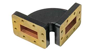
Waveguide flanges
Waveguide junctions
Waveguide bends
Flexible waveguide
Waveguide types & sizes
Waveguides, as the name implies, transfer power by guiding and electromagnetic wave though the waveguide. Electromagnetic waves can travel along waveguides using a number of different modes.
The different waveguide modes have different properties and therefore it is necessary to ensure that the correct mode for any waveguide is excited and others are suppressed as far as possible, if they are even able to be supported.
Waveguides are designed to operate at different frequencies, and often using a specific mode. Also any transition from waveguide to another form of feeder may use a transition and this will be designed to ensure that a particular mode is excited.
If a variety of different waveguide modes present and used at the same time, then the wave may propagate differently with the different modes and this may result int he ultimate waveform being distorted if the modes propagate at different rates, etc.
What is a waveguide mode
The way in which the field exists within the waveguide and this governs a number of the properties of the way in which the electromagnetic wave travels along the waveguide.
Accordingly it is very important to understand the different modes that can exist within a waveguide and the effects that they have on the propagation.
It is worth defining what a waveguide mode is so that this can be used to understand what waveguide modes are and how they affect the way in which the waveguide operates.
Waveguide mode definition:
The mode of a waveguide defined as the transverse field pattern whose amplitude and polarization profiles remain constant along the longitudinal or z coordinate of the waveguide.
Using this definition, it is possible to understand a little more about what a waveguide mode is. However it is necessary to look a little further into the different types of waveguide mode.
Waveguide modes
Looking at waveguide theory it is possible it calculate there are a number of formats in which an electromagnetic wave can propagate within the waveguide.
Fundamentally there are two ways in which electromagnetic waves can propagate within a waveguide and tese are summarised below.
These different types of waves correspond to the different elements within an electromagnetic wave.
- TE mode: This waveguide mode is dependent upon the transverse electric waves, also sometimes called H waves, characterised by the fact that the electric vector (E) being always perpendicular to the direction of propagation.
- TM mode: Transverse magnetic waves, also called E waves are characterised by the fact that the magnetic vector (H vector) is always perpendicular to the direction of propagation.
(TEM mode): The Transverse electromagnetic wave cannot be propagated within a waveguide, but is included for completeness.
It is the mode that is commonly used within coaxial and open wire feeders. The TEM wave is characterised by the fact that both the electric vector (E vector) and the magnetic vector (H vector) are perpendicular to the direction of propagation.
Text about the different types of waveguide modes often indicates the TE and TM modes with integers after them: TEm,n.
The numerals M and N are always integers that can take on separate values from 0 or 1 to infinity. These indicate the wave modes within the waveguide.
Only a limited number of different m, n modes can be propagated along a waveguide dependent upon the waveguide dimensions and format.

For each waveguide mode there is a definite lower frequency limit. This is known as the cut-off frequency. Below this frequency no signals can propagate along the waveguide. As a result the waveguide can be seen as a high pass filter.
It is possible for many waveguide modes to propagate along a waveguide. The number of possible modes for a given size of waveguide increases with the frequency.
It is also worth noting that there is only one possible mode, called the dominant mode for the lowest frequency that can be transmitted. It is the dominant mode in the waveguide that is normally used.
It should be remembered, that even though waveguide theory is expressed in terms of fields and waves, the wall of the waveguide conducts current. For many calculations it is assumed to be a perfect conductor.
In reality this is not the case, and some losses are introduced as a result, although they are comparatively small.
Rules of thumb
Although it is always best to have a good theoretical understanding of the different waveguide modes and how they propagate, etc, it is also useful to be able to utilise experience to give some useful first approximations and as a result know what to look for.
There are a number of rules of thumb and common points that may be used when dealing with waveguide modes.
- For rectangular waveguides, the TE10 mode of propagation is the lowest mode that is supported.
- For rectangular waveguides, the width, i.e. the widest internal dimension of the cross section, determines the lower cut-off frequency and is equal to 1/2 wavelength of the lower cut-off frequency.
- For rectangular waveguides, the TE01 mode occurs when the height equals 1/2 wavelength of the cut-off frequency.
- For rectangular waveguides, the TE20, occurs when the width equals one wavelength of the lower cut-off frequency.
Waveguide propagation constant
A quantity known as the propagation constant is denoted by the Greek letter gamma, γ. The waveguide propagation constant defines the phase and amplitude of each component or waveguide mode for the wave as it propagates along the waveguide. The factor for each component of the wave can be expressed by:
Where:
z = direction of propagation
ω = angular frequency, i.e. 2 π x frequency
It can be seen that if propagation constant, γm,n is real, the phase of each component is constant, and in this case the amplitude decreases exponentially as z increases. In this case no significant propagation takes place and the frequency used for the calculation is below the waveguide cut-off frequency.
It is actually found in this case that a small degree of propagation does occur, but as the levels of attenuation are very high, the signal only travels for a very small distance. As the results are very predictable, a short length of waveguide used below its cut-off frequency can be used as an attenuator with known attenuation.
The alternative case occurs when the propagation constant, γm,n is imaginary. Here it is found that the amplitude of each component remains constant, but the phase varies with the distance z. This means that propagation occurs within the waveguide.
The value of γm,n is contains purely imaginary when there is a totally lossless system. As in reality some loss always occurs, the propagation constant, γm,n will contain both real and imaginary parts, αm,n and βm,n respectively.
Accordingly it will be found that:
This waveguide theory and the waveguide equations are true for any waveguide regardless of whether they are rectangular or circular.
It can be seen that the different waveguide modes propagate along the waveguide in different ways. As a result it is important to understand what he available waveguide modes are and to ensure that only the required one is used.
More Antenna & Propagation Topics:
EM waves
Radio propagation
Ionospheric propagation
Ground wave
Meteor scatter
Tropospheric propagation
Antenna basics
Cubical quad
Dipole
Discone
Ferrite rod
Log periodic antenna
Parabolic reflector antenna
Phased array antennas
Vertical antennas
Yagi
Antenna grounding
Installation guidelines
TV antennas
Coax cable
Waveguide
VSWR
Antenna baluns
MIMO
Return to Antennas & Propagation menu . . .


