
Parabolic Reflector Antenna Feed Systems
A variety of different feed techniques can be used with parabolic reflector antennas including: focal feed, Cassegrain, Gregorian, offset feed.
Log periodic antenna includes:
Parabolic / dish antenna basics
Parabolic antenna theory & equations
Parabolic antenna gain & directivity
Parabolic antenna feed systems
It is possible to use one of a variety of different feed arrangements when using a parabolic reflector antenna.
The different feed arrangements provide a considerable degree of flexibility and enable different applications to gain the most from the use of the antenna.
It is worth noting that the actual antenna element within the overall parabolic reflector antenna, i.e. the device that interfaces the transmission line or waveguide containing the radio-frequency energy to free space, is the feed element for the parabolic reflector antenna.
The reflector surface itself is entirely passive but provides the essential reflecting surface for the overall operation of the antenna, providing its characteristic shape, mode of operation and its performance.
The choice of different types of feed system for these antennas means that the optimum feed can be incorporated into the system whether it is for a microwave link, other form of radio communications, for satellite communications or direct broadcast TV, or whatever.
Parabolic reflector feed length
When feeding a parabolic reflector antenna, it is necessary to place the radiating element at the focal point of the reflector.
The parabolic reflector focal point is the point where all reflected waves will be concentrated. If the radiating element of the antenna is placed here the antenna reflection will operate so that the maximum gain is achieved and the correct operation maintained.
The focal length f (distance of focal point from the centre of the reflector) is calculated with the following equation:
Where:
f is the focal length of the reflector
D is reflector diameter in same units as wavelength
c is depth of the reflector
The radiation from the feed element induces a current flow in the conductive reflector surface which, in turn, re-radiates in the desired direction, perpendicular to the directrix plane of the paraboloid.
The feed element can be any one of a multitude of antenna types. Whichever type is used, it must exhibit a directivity that efficiently illuminates the reflector and must have the correct polarization for the application -- the polarization of the feed determining the polarization of the entire antenna system.
The simplest feed is a half-wave dipole which is commonly used at lower frequencies, sometimes in conjunction with a closely coupled parasitic reflector or "splash plate".
At higher frequencies a horn-type becomes more feasible and efficient. To adapt the horn to a coaxial antenna cable, a length of waveguide is used to effect the transition.
There are two dimensions for the parabolic antenna that are of particular importance. These are the focal length, f and the diameter, D. Typically one of the parameters used to specific parabolic antennas is the f / D ratio. As the f/D ratio is often specified along with the diameter, the focal length can be obtained very easily by multiplying its f/D ratio by the specified diameter D.
Parabolic reflector feed types
There are several different types of parabolic reflector feed systems that can be used. Each has its own characteristics that can be matched to the requirements of the application.
- Focal feed - often also known as axial or front feed system
- Cassegrain feed system
- Gregorian feed system
- Off Axis or offset feed
Focal feed system
The parabolic reflector or dish antenna consists of a radiating element which may be a simple dipole or a waveguide horn antenna. This is placed at the focal point of the parabolic reflecting surface. The energy from the radiating element is arranged so that it illuminates the reflecting surface. Once the energy is reflected it leaves the antenna system in a narrow beam. As a result considerable levels of gain can be achieved.
Achieving this is not always easy because it is dependent upon the radiator that is used. For lower frequencies a dipole element is often employed whereas at higher frequencies a circular waveguide may be used. In fact the circular waveguide provides one of the optimum sources of illumination.

The focal feed system is one of the most widely used feed system for larger parabolic reflector antennas as it is straightforward. The major disadvantage is that the feed and its supports block some of the beam, and this typically limits the aperture efficiency to only about 55 to 60%.
Cassegrain feed system
The Cassegrain feed system, although requiring a second reflecting surface has the advantage that the overall length of the dish antenna between the two reflectors is shorter than the length between the radiating element and the parabolic reflector. This is because there is a reflection in the focusing of the signal which shortens the physical length. This can be an advantage in some systems.

Typical efficiency levels of 65 to 70% can be achieved using this form of parabolic reflector feed system
The Cassegrain parabolic reflector antenna design and feed system gains its name because the basic concept was adapted from the Cassegrain telescope. This was reflecting telescope which was developed around 1672 and attributed to French priest Laurent Cassegrain.
Gregorian parabolic reflector feed
The Gregorian parabolic reflector feed technique is very similar to the Cassegrain design. The major difference is that except that the secondary reflector is concave or more correctly ellipsoidal in shape.

Typical aperture efficiency levels of over 70% can be achieved because the system is able to provide a better illumination of all of the reflector surface..
Off axis or offset parabolic reflector antenna feed
As the name indicates this form of parabolic reflector antenna feed is offset from the centre of the actual antenna dish used.
The reflector used in this type of feed system is an asymmetrical segment of the parabolic shape normally used. In this way the focus, and the feed antenna are located to one side of the reflector surface.

The advantage of using this approach to the parabolic reflector feed system is to move the feed structure out of the beam path. In this way it does not block the beam.
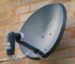
This approach is widely used in home satellite television antennas, which are often relatively small and this would mean that any the feed structure including the low noise box (amplifier, etc) would otherwise block a significant percentage of the beam and thereby reduce the antenna efficiency and signal level.
The offset feed is also used in multiple reflector designs such as the Cassegrain and Gregorian because the small reflector would also suffer the same issues.
One of the advantages of the parabolic reflector antenna is that the feed system can be chosen according to the requirements and there is a variety of different approaches which can be adopted to best meet the requirements for the given application whether it is satellite TV reception, microwave links, satellite communications, general radio communications or for whatever use the antenna is needed.
More Antenna & Propagation Topics:
EM waves
Radio propagation
Ionospheric propagation
Ground wave
Meteor scatter
Tropospheric propagation
Antenna basics
Cubical quad
Dipole
Discone
Ferrite rod
Log periodic antenna
Parabolic reflector antenna
Phased array antennas
Vertical antennas
Yagi
Antenna grounding
Installation guidelines
TV antennas
Coax cable
Waveguide
VSWR
Antenna baluns
MIMO
Return to Antennas & Propagation menu . . .

