
SMA RF Connector
The SMA connector is an effective sub-miniature RF and microwave connector that has a screw fixing to provide reliable connectivity.
RF Coax Connectors Includes:
RF connectors
RF connector specifications
BNC connector
TNC connector
N-type connector
SMA connector
SMB connector
MCX connector
Precision connectors
UHF connector
F-type
Related connector types:
Other connectors
The SMA connector is a semi-precision sub-miniature RF and microwave connector that is extensively used, especially for RF connections within electronic systems for frequencies up to 18 GHz and sometimes more.
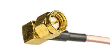
The SMA connector comes in a variety formats, male, female, straight, right-angled, bulkhead fitting and many more enabling it to meet most requirements. Its sub-miniature size also enables it to be used, even within relatively small items of electronic equipment.
Although now well established, the SMA connector is likely to see its use extended as many new RF systems see their operating frequencies extending well into the microwave region.
Although SMA connectors look very similar to the standard household connectors used for domestic satellite TV and other similar applications. These domestic connectors are called F type coax connectors and they have a 75Ω impedance. They have a different diameter and cannot mate with SMA connectors - they would need a special adaptor and then there would be an impedance mismatch.
SMA connector basics
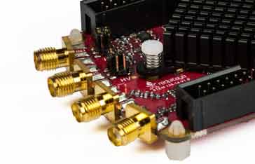
The SMA connector is a sub-miniature coaxial cable connector and it takes its name from the words Sub-Miniature A connector. It finds many applications for providing connectivity for RF assemblies within equipments where coaxial connections are required. It is often used for providing RF connectivity between boards, and many microwave components including filters, attenuators, mixers and oscillators, use SMA connectors.
The connectors have a threaded outer coupling interface that has a hexagonal shape, allowing it to be tightened with a spanner. Special torque spanners are available to enable them to be tightened to the correct tightness, allowing a good connection to be made without over-tightening them. The torque required is typically 8 inch pounds.
The SMA coaxial RF connector was originally designed in the 1960s by the Bendix Scintilla Corporation and Omni-Spectra Corporation. The first SMA connectors were designed for 141 semi-rigid coax. The original SMA connector was what could be termed a minimal connector because the centre of the coax formed the centre pin for the connection, removing the necessity for a transition between the coax centre conductor and a special connector centre pin. It also had the advantage that the cable dielectric was take directly to the interface without air gaps. The disadvantage of the connector was that only a limited number of connect / disconnect cycles were possible. However for applications where semi-rigid coax was used, it was unlikely that this would be a problem as the installations were normally fixed after initial assemble..
However its use extended to other flexible cables, and full connectors with centre pins were introduced. These connectors were manufactured to high standards and also allowed greater numbers of connect / disconnect cycles to be performed.
SMA connector performance
SMA connectors are designed to have a constant have a 50 ohm impedance across the connector. The SMA connectors were originally designed and specified for operation up to 18 GHz, although some versions have top frequencies of 12.4 GHz, some les and some are specified up to 24 or 26.5 GHz. The higher frequency top limits may need to operate with a higher return loss.
The actual specification for a given connector depends very much on the manufacturer and type - several different classes of quality / performance are available. It is always best to carefully check the connector specification
In general, SMA connectors have a higher reflection coefficient than other connectors used up to 24 GHz. This arises from the difficulty in accurately anchoring the dielectric support, but despite this difficulty, some manufacturers have managed to suitably overcome this problem and are able to specify their connectors for operation to 26.5 GHz.
For flexible cables, the frequency limit is normally determined by the cable and not the connector. This is because the cables accepted by SMA connectors are small and their loss is naturally much greater than that of the connectors, especially at the frequencies at which they are likely to be used.
SMA connector power rating
The power rating for SMA connectors can be important in some instances. The key parameter that determines average power handling capabilities for mated coaxial connectors is its ability to pass high current and keep heat-rise to a moderate temperature.
The heating effect results chiefly from the contact resistance and this is a function of the contact surface area and the way in which the contacts mat together. One key area is the centre contacts - these must be properly formed and mate together well. It should also be noted that the average power rating decreases with frequency because the resistive losses increase with frequency.
Figures for power handling of SMA connectors vary widely between manufacturers but some figures indicate some can handle 500 watts at 1GHz falling to just below 200 watts at 10 GHz, but this is much higher than many people would be confident in passing through them.
SMA connector mechanical details
The SMA connector uses a 1/4-inch diameter, 36-thread-per-inch threaded barrel.
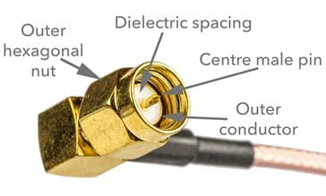
The male connector has a hexagonal nut which measures 5/16 inch, i.e. 0.3125 inch or nominally 8 mm across opposite flats. Accordingly a wrench for a #6 SAE hex nut can be used. This covers the mating outer connection of the male connector which comes into contact with the female outer - this preserves the same inner diameter of the outer conductor across the connector.

The female connector has a barrel without outside threads that mate with the hexagonal nut on the male SMA.
For the central connection, the male connector uses a pin, and the female has a sleeve arrangement that mates with this.
The dielectric is used to support the central pins and is made of polytetrafluoroethylene, PTFE. The PTFE centre of both mating halves makes contact and this preserves the impedance across the connector.
As is standard on all connectors the gender assignment corresponds to the innermost electrical component.
SMA connectors are generally rated for up to 500 mating cycles, but to achieve this it is necessary to properly torque the connector when making the connection. A 5/16-inch torque wrench is required for this, set to 3 - 5 in·lbf (0.3 - 0.6 N·m) for brass, and 7-10 in·lbf (0.8 - 1.1 N·m) for stainless steel connectors.
Make sure that when tightening the nuts on the connector, the body of the connector does not move. If it does, then this causes significant wear on the connector surfaces and reduces the life. It can sometimes be easy to rotate the body of the connector with the nut to manually tighten the connector surfaces - this temptation should be resisted if at all possible.
To help with the proper torqing of the nuts, flats are sometimes also provided on the cable side of the connector assembly so that a second wrench can be used to prevent it from rotating and damaging the joint to the cable.
One of the keys to maintaining the performance and life of the connectors is the cleanliness of the surfaces. Dirt easily accumulates and will cause the contacts to become imperfect. It may also cause slight damages to the surfaces which over time will degrade the performance. It is also advisable to inspect and clean out loose debris from the internal surfaces with compressed air or similar method for dirt and dust removal before mating. This is of paramount importance when these connectors form part of a vector network analysis system.
Reverse polarity SMA connectors
There are also reverse-polarity ("RP") SMA connectors in which the pin and sleeve are swapped; so that the "male" RP-SMA has a centre sleeve surrounded by an inside-threaded barrel, and the "female" RP-SMA has a centre pin and an outside-threaded barrel. See below for a fuller description.
SMA connector performance summary
The highlight performance features and specifications of the SMA connector are detailed in the table below:
| SMA RF Connector Specification Summary |
|
|---|---|
| Parameter | Specification |
| Cable Type | Coaxial |
| Impedance | 50Ω |
| Securing | Screw thread 1/4-36 thread |
| Maximum operating frequency range | Often 0 - 18 GHz, but some manufacturers claim up to 24 GHz or 26.5 GHz |
| Tightening method | 8 mm hex nut on male connector |
| Tightening torque | Typically 3 - 5 in·lbf (0.3 - 0.6 N·m) for brass, and 7-10 in·lbf (0.8 - 1.1 N·m) for stainless steel connectors |
| Design life | 500 mating cycles, but care is needed to keep the mating surfaces clean. |
Connector formats
The SMA connector is available in a variety of forms. The plugs are available in straight and right-angled formats and the sockets are available as cable entry or single pin centre solder contacts. Typically the cable entry types have a single nut fixing to enable them to be attached to a panel. They may also be free connectors. The centre pin types either have a two or four screw fixing capability to enable them to attach to a panel.
More Electronic Components:
Batteries
Capacitors
Connectors
Diodes
FET
Inductors
Memory types
Phototransistor
Quartz crystals
Relays
Resistors
RF connectors
Switches
Surface mount technology
Thyristor
Transformers
Transistor
Unijunction
Valves / Tubes
Return to Components menu . . .


