
Superheterodyne Spectrum Analyzer: Sweep Spectrum Analyser
The superheterodyne spectrum analyzer or sweep / swept spectrum analyzer was the first type to be used and gives excellent insight into the basic operation and concepts of analyzers.
Spectrum Analyzer Tutorial Includes:
What is a spectrum analyzer
Spectrum analyzer types and technologies
Superheterodyne / sweep spectrum analyzer
FFT spectrum analyzer
Realtime spectrum analyzer
USB spectrum analyzer
Spectrum analyzer tracking generator
Specifications
Spectrum analyzer operation
Noise figure measurements
Phase noise measurements
Pulsed signal spectrum analysis
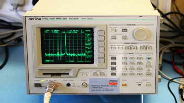
The suerheterodyne spectrum analyser which is also referred to by the name sweep or swept spectrum analyzer was the first form of spectrum analyzer to be used.
In essence the superheterodyne spectrum analyzer or sweep / swept spectrum analyzer is a form of radio receiver with a display at the output indicating the output level. The receiver is tuned or scanned over the required range and the filters are chosen to accept the required signal bandwidth.
The spectrum analyser uses the superhet principle used in many radio receivers as the underlying principle on which its operation depends. The superhet principle uses a mixer and in addition to a locally generated or local oscillator to translate the frequency.
Advantages & disadvantages of a sweep / swept spectrum analyzer
The sweep or swept spectrum analyzer has a number of advantages and disadvantages when compared to other types of spectrum analyzer. When choosing which type will be suitable, it is necessary to understand the differences between them and their relative merits.
The other main type of spectrum analyzer uses digital technology and relies on Fast Fourier Transforms – hence it is often referred to as an FFT analyzer.
Advantages of superheterodyne spectrum analyser technology
- Wide bandwidth: As a result of the superheterodyne principle this type of spectrum analyzer is able to have very wide scan spans. The span of a scan may extend to several GHz.
- Able to operate over wide frequency range: Using the superheterodyne principle, this type of spectrum analyzer is able to operate up to very high frequencies - many extend their coverage to many GHz as it is possible to convert from very high frequencies down to the processing band.
Disadvantages of superheterodyne spectrum analyzer technology
- Cannot measure phase: The superheterodyne or sweep spectrum analyzer is a scalar instrument and unable to measure phase - it can only measure the amplitude of signals on given frequencies.
- Cannot measure transient events: FFT analyzer technology is able to sample over a short time and then process this to give the required display. In this way it is able to capture transient events. As the superheterodyne analyzer sweeps the bandwidth required, this takes longer and as a result it is unable to capture transient events effectively.
FFT spectrum analyzers used to be more expensive than the more traditional swept or superheterodyne spectrum analzers. However technology has moved on and now there is little cost difference in many instances. Typically most modern spectrum analyzers will use digital processing, although they may still use the superheterodyne principle to provide the required frequency range.
Sweep spectrum analyser basics
The swept spectrum analyser uses the same superheterodyne principle used in many radio receivers as the underlying principle on which its operation depends. The superheterodyne principle uses a mixer and a locally generated local oscillator signal to translate the frequency.
The mixing principle used in the analyzer operates in exactly the same manner as it does for a superheterodyne radio.
Note on RF Mixing / Multiplication:
RF mixing or multiplication is a key RF technique. Using a local oscillator, it enables signals to be translated in frequency, thereby enabling signals to be converted up and down in frequency.
Read more about RF mixing / multiplication
The signal entering the front end is translated to another frequency, typically lower in frequency. Using a fixed frequency filter in the intermediate frequency section of the equipment enables high performance filters to be used, and the analyzer or receiver input frequency can be changed by altering the frequency of the local oscillator signal entering the mixer.
Although the basic concept of the spectrum analyzer is exactly the same as the superheterodyne radio, the particular implementation differs slightly to enable it to perform is function.

The frequency of the local oscillator governs the frequency of the signal that will pass through the intermediate frequency filter. This is swept in frequency (linearly increasing in frequency) so that it covers the required band. The sweep voltage used to control the frequency of the local oscillator also controls the sweep of the scan on the display. In this way the position of the scanned point on the screen relates to the position or frequency of the local oscillator and hence the frequency of the incoming signal. Also any signals passing through the filter are further amplified, detected and normally converted to a logarithmic scale because of the enormous range of input levels received and then it is passed to the display Y axis.
Elements of a sweep spectrum analyzer
Although the basic concept of the sweep spectrum analyser is fairly straightforward a few of the circuit blocks may need a little further explanation.
RF attenuator: The first element a signal reaches on entering the test instrument is an RF attenuator. Early models used a manually switched attenuator, but modern analyzers normally have this controlled by the processor in the test instrument. Its purpose is to adjust the level of the signal entering the mixer to its optimum level. If the signal level is too high, not only may the reading fall outside the display, but also the mixer performance may not be optimum. It is possible that the mixer may run outside is specified operating region and additional mix products may be visible and false signals may be seen on the display.
In fact when false signals are suspected, the input attenuator can be adjusted to give additional attenuation, e.g. +10 dB. If a signal on the display level falls by more than this amount then it is likely to be an unwanted mix product and insufficient RF attenuation was included for the input signal level.
The input RF attenuator also serves to provide some protection to very large signals. It is quite possible for very large signals to damage the mixer. As these mixers are very high performance components, they are not cheap to replace and they are relatively easily damaged. A further element of protection is added. Often the input RF attenuator includes a capacitor and this protects the mixer from any DC that may be present on the line being measured.
Low pass filter and pre-selector: This circuit follows the attenuator and is included to remove out-of-band signals. This filter in the spectrum analyzer prevents unwanted signals from mixing with the local oscillator and generating unwanted responses at the IF. These would appear as signals on the display and as such must be removed.
Microwave spectrum analyzers often replace the low pass filter with a more comprehensive pre-selector. This allows through a band of frequencies, and its response is obviously tailored to the band of interest.
Mixer: The mixer is naturally key to the success of the analyser. As such the mixers are high performance items and are generally very expensive. They must be able to operate over a very wide range of signals and offer very low levels of spurious responses. Any spurious signals that are generated may give rise to spurious response that will be displayed along with the real signals on the display. Thus the dynamic range performance of the mixer is of crucial importance to the analyser as a whole.
Great care must be taken when using a sweep spectrum analyzer not to feed excessive power directly into the mixer otherwise damage can easily occur. This can happen when testing radio transmitters where power levels can be high and accidentally turning the attenuator to a low value setting so that higher power levels reach the mixer. As a result it is often good practice to use an external fixed attenuator that is capable of handling the power. Damage to the mixer will render the spectrum analyzer unserviceable and require repair which is generally costly.
- IF amplifier: Signals leaving the mixer are generally low level and they need to be amplified. The gain of the stage is adjustable, typically in 10dB stages. Altering the gain here alters the position of the signal on the vertical scale of the analyzer. The IF gain has to be used in conjunction with the RF gain control – in modern analyzers the two are normally linked and adjusted to give the best overall performance. Too high a level of IF gain will increase the front end noise level which may result in low level signals being masked. Accordingly the RF gain control should generally be kept as high as possible without overloading the mixer. In this way the noise performance of the overall test instrument is optimised.
- IF filter: The IF filters restrict the bandwidth that is viewed, effectively increasing the frequency resolution. However this is at the cost of a slower scan rate. Narrowing the IF bandwidth reduces the noise floor and enables lower level spurious signals to be viewed.
- Local oscillator: The local oscillator within the spectrum analyzer is naturally a key element in the whole operation of the unit. Its performance governs many of the overall performance parameters of the whole analyser. It must be capable of being tuned over a very wide range of frequencies to enable the analyzer to scan over the required range. It must also have a very good phase noise performance. If the oscillator has a poor phase noise performance then it will not only result in the unit not being able to make narrow band measurements as the close in phase noise on the local oscillator will translate onto the measurements of the signal under test, but it will also prevent it making any meaningful measurements of phase noise itself - a measurement being made increasingly these days.
- Ramp generator: The ramp generator drives the sweep of the local oscillator and also the display. In this way the horizontal axis of the display is directly linked to the frequency. In other words the ramp generator is controlled by the sweep rate adjustment on the spectrum analyser.
Envelope or level detector: The envelope detector converts the signal from the IF filter into a signal voltage that can be passed to the display. As the level detector has to accommodate very large signal differences, linearity and wide dynamic range are essential.
The type of detector may also have a bearing on the measurement made. Whether the detector is an average level detector or whether it provides an RMS value.
An RMS detector calculates the power for each pixel of the displayed trace from samples allocated to the pixel, i.e. for the bandwidth that the pixel represents. The voltage for each sample is squared, summed and the result divided by the number of samples. The square root is then taken to give the RMS value.
For an average value, the samples are summed, and the result is divided by the number of samples.
- Display: In many respects the display is the heart of the test instrument as this is where the signal spectra are viewed. The overall display section of the spectrum analyser contains a significant amount of processing to enable the signals to be viewed in a fashion that is easy comprehend. Items such as markers for minimum signal, maximum peak, auto peak, highlighting and many more elements are controlled by the signal processing in this area. These features and many more come as the result of significant increases in the amount of processing provided.
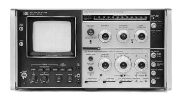
As for the display screens themselves, cathode ray tubes were originally used, but the most common form of display nowadays are forms of liquid crystal displays. The use of liquid crystal displays does have some limitations, but overall with the level of development in this technology they enable the required flexibility to be provided.
The superheterodyne spectrum analyser, or as it is also called the sweep spectrum analyser is still used although it has been overtaken by spectrum analyzers using digital FFT technology. Nevertheless it services to illustrate the principle of the spectrum analyzer, and often older units may be available in some laboratories.
More Test Topics:
Data network analyzer
Digital Multimeter
Frequency counter
Oscilloscope
Signal generators
Spectrum analyzer
LCR meter
Dip meter, GDO
Logic analyzer
RF power meter
RF signal generator
Logic probe
PAT testing & testers
Time domain reflectometer
Vector network analyzer
PXI
GPIB
Boundary scan / JTAG
Data acquisition
Return to Test menu . . .

