
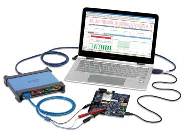
USB Oscilloscope: PC based scope
PC & USB oscilloscopes provide high performance test instruments in a small space and for a comparatively low cost by using the user interface and some processing of a computer.
Scope types includes:
Analogue scope
Analogue storage scope
Digital phosphor scope
Digital scope
USB / PC scope
Mixed Signal Oscilloscope MSO
Sampling scope
Oscilloscope Tutorial Includes:
Oscilloscope basics
Oscilloscope types summary
Specifications
How to use an oscilloscope
Scope triggering
Oscilloscope probes
Oscilloscope probe specifications
PC based oscilloscopes including USB scopes have become a very popular way of providing a high performance oscilloscope for low cost and in a small package.
In may instances a computer will be available in an environment where electronic equipment is to be tested, and therefore using the processing power, screen and power supply of the PC or other computer makes sense, saving on cost and space.
In view of the demand for USB oscilloscopes, a large variety is available, offering the full range of capabilities from entry level USB scopes right up to sampling oscilloscopes with bandwidths extending into the GHz region. These test instruments enable considerable cost savings to be made without compromising on performance dependent upon the USB scope selected
Choice of USB for PC scopes
Using the Universal Serial Bus, USB for the means of connecting a scope to a PC makes absolute sense, although it is not the only method.
It is possible for scopes using personal computers, PCs, to use a variety of methods to link to PCs. However in recent years USB has become standard on virtually all computers and as a result it does not require the use of an additional card like a Firewire card, etc to use one of these test instruments.
Using USB means that it is possible to use a scope using the PC processing power on virtually any PC.
The other advantage is that having a digital USB scope design enables the advantages and cost savings of quantity can be made. Fewer variants are required for different interfaces, and therefore it is possible to focus on optimising the test instrument design for USB.
It is also interesting to note that many boxed digital oscilloscopes adopt exactly the same approach and have the same basic circuit blocks, the only real difference is that the USB scope uses an external PC or other computer for the control and display.
PC USB scope basics
One of the key elements of the PC oscilloscope is naturally the USB link. This provides a convenient and sufficiently high speed data link by which the USB scope and computer can communicate.
Although the test equipment from different manufacturers and those at different positions within the ranges from manufacturers will differ, there are some common aspects of these scopes that can be outlined.
There are two main approaches that are used for USB oscilloscopes, one providing much cheaper, but lower performance scopes, and the other providing a much more satisfactory solution.
1) Simple microprocessor based USB scope
This form of USB oscilloscope uses an on-board microprocessor to control and undertake the measurements, but in this simple format there are some severe limitations.
In terms of its operation, the incoming waveform enters the scope and undergoes analogue conditioning: attenuation; amplification; impedance matching, as required. It is then passed into an analogue to digital converter, ADC and the data is presented to a microprocessor.

In view of the architecture of the processor, typically the processor organises the data so that it can be sent to the computer for most of the processing. This means that a lot of data needs to be passed to the computer over the USB link and this can prove to be a bottleneck. One of the main issues is that it is not possible to guarantee the start of the trigger, so it is possible to miss an important event on the signal. This could result in a lot of time being spent tracking an issue onto e signal because it cannot be seen by the scope
2) FPGA based USB scope
In order to significantly improve the performance of USB oscilloscopes, FPGAs or sometimes CPLDs are used. These enable much more processing to be achieved within the USB scope itself and also in a much shorter time. These devices can be configured to perform the exact tasks required and therefore they can process the data much faster and they can handle much more data to ensure the best displays of the waveforms are obtained.
One important area where this can be experienced is for the triggering, where the much faster operation means that the scope is able to trigger properly, even at the full scope rate.
Using FPGA based USB scopes, the data is processed in a parallel manner, data is stored in the USB scope itself, and the PC is fundamentally used for signal display and control. The USB scope processes the data that is captured and then passes the waveform to be displayed to the PC or other computer using a lossless format over the USB link. In this way the USB link does not form a bottleneck, and the scope which has been designed for processing the captured waveform data is able to achieve this in the most effective manner.

Data is passed through the analogue conditioning so that any attenuation, gain, and impedance matching etc, can be provided. The resulting waveform is then passed to the analogue to digital converter.
The ADC may have one or many cores - if it has multiple cores then the data is typically streamed in parallel to the FPGA and into memory. With data stored in this way, it is possible to process it in a variety of ways, recalling the data from memory as required.
Many oscilloscopes, both USB and boxed scopes offer logic analysis or digital channels. These do not require the same analogue processing and they can be passed directly into the FPGA, obviously via protection circuitry. Scopes with this capability are typically referred to as MSOs or mixed signal oscilloscopes.
Once the waveform has been processed, the image to be displayed can be passed over the USB interface to the PC. As it is only the processed data that is based to the PC, there is no bottleneck on the USB or other interface and this means that the performance is not limited by that of the USB interface. It is also passed over in a lossless format to ensure that the all impulses / transients can be seen. In some scopes decimated data may be sent and this can give rise to imperfections in the displayed waveform that could result in transients being missed.
PC USB scope advantages / disadvantages
There are many advantages and disadvantages to using a PC based USB oscilloscope. These need to be balanced when deciding whether to use or buy one of these test instruments.
Advantages of USB / PC based scope
- Cost effective: One of the big advantages of using a USB oscilloscope is that it is a very cost effective way of buying an oscilloscope. The overall test equipment utilises many aspects of a computer that is likely to be available already. Power supply, display and processing power are all available within the PC and this means these do not need to be replicated within the USB scope.
- Easy to set-up and use : Using a USB interface means that connecting the PC and the scope together is particularly easy. It is a well tried and tested interface that is simple to set up. Normally the software used with the scope is also designed to be very easy to implement.
- Large screen: Most PCs, whether a laptop or desktop have a good sized screen, making the waveform images easy to see.
- Utilises existing equipment : USB oscilloscopes utilise PCs which are likely to be already available. This means that it is unlikely that it will be necessary to buy a new one particularly for that role.
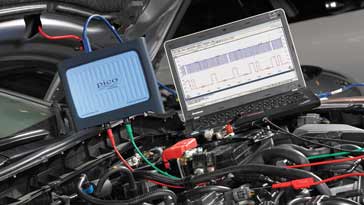
- Portable : The USB oscilloscopes are very much smaller than dedicated oscilloscopes. For field service, many engineers will already carry a laptop, so the fact that the USB scope is much smaller than a dedicated oscilloscope provides a real advantage.
- Performance: The performance that can be attained by PC based oscilloscopes is improving all the time. Top end USB oscilloscopes, for example, can match the performance of the self-contained items of test equipment that are available. Dependent upon the model chosen, these USB scopes can match the top end standard scopes and at much less cost.
Disadvantages of USB / PC based scope
- Requires a PC: The fact that a USB scope requires a PC can be an advantage in some instances, but in others it can be a disadvantage if one is not already available.
- Bottom end scope manufacturers can cut corners: Like all test instruments, you can get what you pay for. Some bottom end USB scopes from less well known makes can cut corners to reduce costs and there can be issues with the performance. Go to a well known brand, and the performance will be assured.
Key points to consider when choosing a USB oscilloscope
There are very many USB oscilloscopes on the market, some of which are much better than others. Accordingly when selecting a USB scope it is necessary to ensure that the best choice is made and below are a few pointers to bear in mind:
- Ensure trigger is digital: In some USB scopes, or in fact any digital scopes, the trigger can be developed directly from the analogue signal, whereas within others it is taken from the digital data held int he scope. If a wholly digital trigger is incorporated within the scope, this enables far higher levels of accuracy and flexibility to be achieved. False triggering, noise and other issues can be minimised with digital triggers and the triggering can be set for the middle of the waveform, etc so that the waveform before and after the trigger point can be seen.
- Ensure an FPGA based USB scope is selected: USB scopes based around FPGA technology are able to provide much higher levels of performance. The microprocessor based ones often advertise sample rates of 48 MHz, 96MHz, or submultiples and these typically have a limited bandwidth.
- Resolution: One key specification for digital scopes is the resolution that can be obtained. Some low end scopes may only offer eight or ten bit resolution. When displaying waveforms on a computer screen using lower resolution scopes, it is possible to detect the lack of detail. Sometimes the waveforms may appear jagged as the individual bits can be seen. It is also possible to lose detail, especially when looking at a small voltage in the presence of a much larger one. Some scopes offer much greater levels of resolution and these are able to provide much greater detail.
- Bandwidth: When looking at waveforms it is necessary to ensure that the scope bandwidth is sufficiently high to capture the waveform and any harmonics it may contain. Often a rule of thumb referred to as the Five Times Rule is used. With this the bandwidth of the oscilloscope should be five times the highest frequency component in the signal. Using this rule, the error due to the frequency limitations will be less than ±2%.
- Memory depth: When selecting a USB scope, sure that it has sufficient memory to capture and store the waveforms needed. The greater the memory depth the more signal it is possible to capture at the highest sample rate.
With a 1MSa per channel an oscilloscope can capture 1 ms or time with a 1GSa/s sample rate. Thus sufficient memory must be available to capture this amount of data. This gives an indication of what might be needed. - Function generator / AWG capability: Using the capabilities of the FPGA, it is easy to incorporate a function generator that can produce a variety of waveforms. Sime scopes have the full arbitrary waveform generation capability, so it is possible to generate or upload any required waveform.
- Consider PC type: Most USB scopes will be able to operate with a Windows based PC, however some may want to use the scope with either an Apple Mac using iOS, or they will want to use Linux. Check the USB scope can cater for the operating system to be used.
There are many advantages to using a PC based or USB oscilloscope, but these need to be carefully considered before making any final choice.
More Test Topics:
Data network analyzer
Digital Multimeter
Frequency counter
Oscilloscope
Signal generators
Spectrum analyzer
LCR meter
Dip meter, GDO
Logic analyzer
RF power meter
RF signal generator
Logic probe
PAT testing & testers
Time domain reflectometer
Vector network analyzer
PXI
GPIB
Boundary scan / JTAG
Data acquisition
Return to Test menu . . .


