
GPIB Cables
Details about IEEE 488 or GPIB cables describing their format, construction and use for GPIB inter-connections.
GPIB / IEEE 488 Bus Includes:
GPIB / IEEE 488 bus
GPIB operation / commands / protocol
IEEE 488.2
How to Use GPIB / IEEE 488
GPIB / IEEE 488 cables
GPIB / IEEE 488 connectors
GPIB / IEEE 488 pinout / pin connections
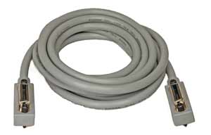
GPIB cables are widely available and easy to use.
They are characterised by the connectors which contain the screwlocks and the fact that each end of the cable has both male and female connectors, making them rather bulky.
However the cables are easy to use and enable controllers and instruments to be linked in a very flexible fashion.
GPIB cable basics
In practice the GPIB interface is very easy to use. Ready-made GPIB cables are widely available even if they appear to be a little expensive. However these GPIB cables are fully screened and have the correct lines as twisted pairs.
Fully GPIB compatible cables have the following details:
- 24 conductors with twisted pairs.
- Braid Shield.
- Centronics style, Amphenol type 57 connectors, 24 pin male to female piggy back connectors to enable easy daisy chaining.
- Metric mating hardware, M3.5 x 0.6 now used as standard and finished in black - previously UTS thread was used and finished in chrome / silver colour. Note: the two types do not mate.
The use of these fully specified cables ensures that the system is as free as possible from the effects of spurious noise and the maximum data rates can be achieved.
Low specification alternative GPIB cable
A cheap and convenient alternative for GPIB cables is available in the form of insulation displacement connectors. While cables made in this way are much cheaper they are not screened and do not conform to the GPIB / IEEE 488 specifications. In view of this they should only be used where there are a very limited number of instruments, where data rates are likely to be low, for long runs, and where electrical noise is not likely to be a problem. If a cable of this nature is used then it is worth being aware that it could be the cause of random errors when the system is operating.
Cabling restrictions
Although there is a considerable degree of flexibility when setting up a GPIB system, there are some restrictions on the way the GPIB cables are set up.
| GPIB Cabling Restrictions | |
|---|---|
| Parameter | Details |
| Maximum number of instruments | 15 |
| Maximum bus length | 20 metres |
| Max distance between instruments | 2 metres average, 4 metres maximum in any instance |
| Configurations | Star or linear or any combination |
Standard GPIB cable lengths
Although a variety of GPIB cable products are available, typically they are available in set lengths. The most common lengths for GPIB cables are: 1 metre and 2 metres - with two metres being the most common..
Longer GPIB cables are not normally available in view of the GPIB overall bus restrictions. Some 0.5 metre GPIB cables are available, but these are often too short for many applications in view of the lack of cable flexibility.
Hints and tips for use
Although the GPIB cables are easy to use, a few hints and tips may save time.
- Beware reliability: Although the majority of GPIB cables may be well made, they can form a major source of failures. As they carry a large number of individual wires, they do not flex easily and wires can come adrift in the cable assembly. If in doubt try another cable, and quarantine or remove any suspect cables.
- Limit cables on one node: Piggy backing cables together makes the use of GPIB very easy. However if too may cables are piggy backed on one node, the weight of the cables can place a significant strain on the connectors near the base. Limit the number of cables connected to any one node to prevent this strain occurring and the possible unreliability that may result.
- Weight: In view of the number of wires within any GPIB cable, they are relatively bulky and have more weight than many cables. Beware not to place too much strain on connections by supporting the cables where appropriate.
- Flexing: One of the chief causes of unreliability in GPIB cables is flexing close to the connector. However well they have been made, flexing at this point will ultimately lead to failures in the cable as connections onto the connectors themselves break. To ensure reliability is retained, it is advisable to keep the cable from flexing, especially at or towards the connectors as much as possible.
- Use old cables with care: In view of the issues with unreliability, old cables should be used with caution. They may have been previously discarded with good reason.
More Test Topics:
Data network analyzer
Digital Multimeter
Frequency counter
Oscilloscope
Signal generators
Spectrum analyzer
LCR meter
Dip meter, GDO
Logic analyzer
RF power meter
RF signal generator
Logic probe
PAT testing & testers
Time domain reflectometer
Vector network analyzer
PXI
GPIB
Boundary scan / JTAG
Data acquisition
Return to Test menu . . .

