
What is GPIB / IEEE 488 Bus
GPIB is an interface bus or connection system used primarily to link electronics test equipment to a central controlled to run automated tests although it can be used for many data communication requirements.
GPIB / IEEE 488 Bus Includes:
GPIB / IEEE 488 bus
GPIB operation / commands / protocol
IEEE 488.2
How to Use GPIB / IEEE 488
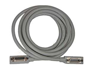
GPIB / IEEE 488 cables
GPIB / IEEE 488 connectors
GPIB / IEEE 488 pinout / pin connections
The GPIB or General Purpose Interface Bus or IEEE 488 bus is still one of the more popular and versatile interface standards available today.
GPIB is widely used for enabling electronics test equipment to be controlled remotely, although it was also used in a many other applications including general computer communications.
It can be used to control a host of test instruments: everything from digital multimeters and signal generators of all sorts to switching matrices, spectrum analyzers, vibration meters . . . in fact any form of electronics test equipment. At one time it even became popular for linking computers to their printers and many low cost printers used GPIB.
Today most bench electronics test equipment has either a GPIB option or are fitted with it as standard. Even though it has been surpassed by other technologies, it is still widely used and often fitted as a basic option.
GPIB origins
Originally GPIB was named the HP-IB. This came from the words: Hewlett Packard Interface Bus as it was originally introduced by HP for controlling their electronics test equipment (later the test equipment arm of HP became a separate company with the name Agilent and later still Keysight).
As it has gained popularity, the HPIB as it was initially called has gained a number of other names over the years. GPIB has been adopted by a number of major institutions that have given it their numbers. The Institute of Electrical and Electronic Engineers in the U.S.A. have given it their specification number 488 in 1978, and as a result it is sometimes referred to as the IEEE 488 bus or IEEE488 bus.
The IEEE specification defines the basic mechanical electrical and protocol parameters. The IEEE 488.2 standard released in 1987 defines the related software specifications.
Other organisations have also adopted the standard as well and given it their own numbers which will occasionally be seen.. The American National Standards Institute as has the IEC. The IEC standard numbers were IEC-60625-1 and IEC-60625-2, but these were later replaced by IEC-60488 to provide number compatibility.
Despite the proliferation of names and numbers for it, the specifications are all virtually the same and can be used interchangeably. Of all the names GPIB is the most common, followed by IEEE 488 bus, referring to the most commonly used standard for the bus.
In 2004 the IEEE and IEC combined their own standards into combined work: IEEE/IEC standard IEC-60488-1. The IEEE 488.2 standard was similarly combined and became IEC-60488-2.
Basic GPIB concept
The GPIB or IEEE 488 bus is a very flexible system, allowing data to flow between any of the instruments on the bus, at a speed suitable for the slowest active instrument. Up to fifteen instruments may be connected together with a maximum bus length not exceeding 20 m.
A further requirement for the bus is that there must also be no more than 2 m between two adjacent test instruments.
It is possible to purchase GPIB cards to incorporate into computers that do not have the interface fitted. As GPIB cards are relatively cheap, this makes the inclusion of a GPIB card into the system a very cost effect method of installing it. That said, the falling usage of GPIB means that GPIB cards are not nearly as widely available as they used to be.
Devices have a unique address on the bus. Test instruments are allocated addresses in the range 0 to 30, and no two instruments on the same bus are allowed to have the same address. The addresses on the instruments can be changed and this may typically be done via the front panel, or by using switches often located on the rear panel.
Active extenders are available and these items allow longer buses: up to 31 devices theoretically possible, along with a greater overall length dependent upon the extender.
In the original HPIB protocol, transfers utilise three wire handshaking system. Using this the maximum data rate achievable is around 1 Mbyte per second, but this is always governed by the speed of the slowest device. A later enhancement often referred to as HS-488 relaxes the handshaking conditions and enables data rates up to about 8 Mbytes / second.
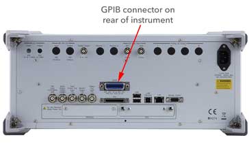
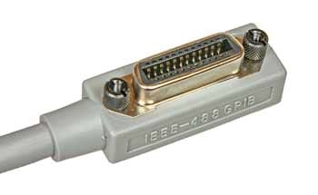
The connector used for the IEEE 488 bus is standardised as a 24-way Amphenol 57 series type. This provides an ideal physical interface for the standard. The IEEE 488 or GPIB connector is very similar in format to those that were used for parallel printer ports on PCs although the type used for the GPIB has the advantage it has been changed so that several connectors can be piggy-backed. This helps the physical setting up of the bus and prevents complications with special connection boxes or star points.
Within IEEE 488, the equipment on the bus falls into three categories, although items can fulfil more than one function:
- Controller: As the name suggests, the controller is the entity that controls the operation of the bus. It is usually a computer and it signals that instruments are to perform the various functions. The GPIB controller also ensures that no conflicts occur on the bus. If two talkers tried to talk at the same time then data would become corrupted and the operation of the whole system would be seriously impaired. It is possible for multiple controllers to share the same bus; but only one can act as a controller at any particular time.
- Listener: A listener is an entity connected to the bus that accepts instructions from the bus. An example of a listener is an item such as a printer that only accepts data from the bus. It could also be a test instrument such as a power supply or switching matrix that does not take measurements.
- Talker: This is an entity on the bus that issues instructions / data onto the bus.
Many items of test equipment will fulfil more than one function. For example a voltmeter which is controlled over the bus will act as a listener when it is being set up, and then when it is returning the data, it will act as a talker. As such it is known as a talker / listener.
Often GPIB cards can be used in a variety of roles, but these GPIB cards are most often used as controllers as they tend to reside in the controlling computer. Most test instruments that might be intended for use with the GBIP interface would have this fitted as standard and would therefore not require and additional GPIB card.
GPIB features / parameters summary
Although the full specification for GPIB / IEEE 488 is held by the IEEE and IEC, there key features for the bus can be seen in the short table below.
| IEEE 488 bus / GPIB Features Summary |
|
|---|---|
| Parameter | Details |
| Max length of bus | 20 metres |
| Max individual distance between instruments | 2 metres average 4 metres maximum in any instance. |
| Maximum number of instruments | 14 plus controller, i.e. 15 instruments total with at least two-thirds of the devices powered on. |
| Data bus width | 8 lines. |
| Handshake lines | 3 |
| Bus management lines | 5 |
| Connector | 24-pin Amphenol (typical) D-type occasionally used. |
| Max data rate | ~ 1 Mbyte / sec (HS-488 allows up to ~8Mbyte / sec). |
Advantages & disadvantages of GPIB
Like any other technology, GPIB has advantages and disadvantages that need to be weighed up when considering its use.
Advantages
- Simple & standard hardware interface
- Interface present on many bench instruments
- Rugged connectors & connectors used (although some insulation displacement cables appear occasionally).
- Possible to connect multiple instruments to a single controller
Disadvantages
- Bulky connectors
- Cable reliability poor - often as a result of the bulky cables.
- Low bandwidth - slow compared to more modern interfaces
- Basic IEEE 422 does not mandate a command language (SCPI used in later implementations but not included on all instruments.
GPIB capability is included on a large number of bench instruments, but when opting to use the facility to build a system, it is necessary to consider all the advantages and disadvantages before committing time and cost to its use.
GPIB / IEEE 488 today
The GPIB has been available since the late 1960s, but despite its age, it is still a valuable tool that is widely used throughout the industry. Most bench instruments have GPIB fitted as standard or as an option making it easy to use test equipment in a variety of applications apart from being dedicated to use in an ATE test stack. Additionally GPIB or IEEE 488 is used in a wide number of other applications including data acquisition.
Although computers tend not to have GPIB interfaces fitted as standard today, a GPIB card may be bought and installed. In view of its flexibility and convenience and it is likely to remain in widespread use for some years to come.
More Test Topics:
Data network analyzer
Digital Multimeter
Frequency counter
Oscilloscope
Signal generators
Spectrum analyzer
LCR meter
Dip meter, GDO
Logic analyzer
RF power meter
RF signal generator
Logic probe
PAT testing & testers
Time domain reflectometer
Vector network analyzer
PXI
GPIB
Boundary scan / JTAG
Data acquisition
Return to Test menu . . .


