
High & Low Pass LC RF Filter Design
High and low pass LC RF filters are commonly used to provide attenuation of unwanted signals - basic design concepts and circuits are relatively easy to grasp.
RF Filters Includes:
RF filters - the basics
Filter specifications
RF filter design basics
High & low pass filter design
Constant-k filter
Butterworth filter
Chebychev filter
Bessel filter
Elliptical filter
Crystal filter
Both high and low pass filters are widely used within RF circuits - also for RF applications they are normally based around both inductors and capacitors.
These LC filters provide much better performance than just RC filters and accordingly they tend to be used for RF applications.
The design of both low and high pass LC filters can be relatively straightforward. However when using the tabular approach with tables of values scaled for the particular frequency and impedance, the low pass filter design is normally the starting point, and this is transformed to provide the equivalent high pass filter.
Low pass filter design techniques
When designing either a high or low pass RF filter, normally a low pass filter forms the starting point. If a high pass filter is required the low pass configuration is transformed to provide the high pass filter design.
Once the basic design has been achieved, the high pass filter design can then be effected by easily transforming the values to give the required high pass filter functionality.
By using the low pass filter design as the starting point for high pass filters, the number of tables required for the design of any given level of performance can be halved. The transformation from low pass filter design to high pass is relatively straightforward and cut the number of tables required by half.
High & low pass filters
In many respects low pass and high pass filters are the inverse of each other. The low pass filter passes signals below the cut-off frequency, and not appreciably attenuating the signal within the pass-band as shown.

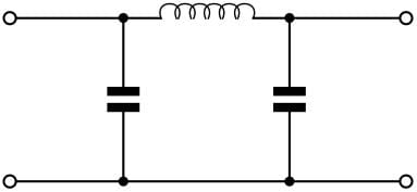
To provide a low pass response, the filter typically has series inductors and parallel capacitors. A Pi (Π) section would look like that in the diagram below.
Conversely a high pass filter passes signals above the cut-off frequency, and attenuates those below it as shown.

To produce the high pass response, the inductors and capacitors are exchanged from the low pass filter to form the high pass filter. Accordingly there is a series capacitor, and two inductors from the line to ground.

In view of the similarities, the design and values are linked. Accordingly it has been possible to only generate the table of values for low pass filters and then transform them for the
High pass filter design basics
Although there are programmes that will enable the design of a high pass filter circuit, often a more manual method may be required. The typical approach that is used is to design a low pass filter, and then transform this to a high pass filter design.
When choosing the basic requirements for the high pass filter design, elements such as in-band ripple will remain the same.
It is possible to utilise the same response curves by inverting the f/fc axis. This is because the response of the high pass filter is the inverse of the low pass filter in frequency terms. In other words in a high pass filter design, it is necessary to measure the attenuation at frequencies at a proportion below the cut-off frequency rather than above the cut-off frequency. For example an attenuation level at 1/2 the cut-off frequency may be required for a high pass filter design rather than 2 times the frequency.
Using this information and any other it is possible to find a response that satisfies the requirements. The next stage is to determine the values of the circuit elements for the normalised low pass filter version.
Circuit element transformation
After the circuit elements have been determined, the next stage in the high pass filter design is to transform the circuit elements from the low pass version into one for the high pass filter design.

To complete the high pass filter design, the element values are easily determined by replacing each filter element with an element of the opposite type, i.e. replace a capacitor by an inductor and an inductor by a capacitor. The value of the capacitor is equal to the reciprocal of the inductor and vice versa, i.e. Ln = 1/Cn and Cm = 1/Lm.

The values in the above example and purely fictional and only to be used for the purposes of the explanation.
It can be seen that it is quite easy to create a high pass filter from a low pass RF filter design. As the transformation is so easy, it means that only one set of data is required. This is normally that needed for the low pass filter.
More Essential Radio Topics:
Radio Signals
Modulation types & techniques
Amplitude modulation
Frequency modulation
OFDM
RF mixing
Phase locked loops
Frequency synthesizers
Passive intermodulation
RF attenuators
RF filters
RF circulator
Radio receiver types
Superhet radio
Receiver selectivity
Receiver sensitivity
Receiver strong signal handling
Receiver dynamic range
Return to Radio topics menu . . .


