Digital PLL Frequency Synthesizer
The digital PLL RF frequency synthesizer works by placing a digital frequency divider into PLL between the VCO & phase detector and by changing the division ratio of the divider, the output frequency changes.
Frequency Synthesizer Tutorials Includes:
Synthesizer basics
PLL / indirect synthesizer
PLL digital synthesizer
PLL analogue synthesizer
Multiloop synthesizer
Fractional N synthesis
Synthesizer phase noise
How to design synthesizer for low phase noise
Direct digital synthesizer, DDS
The digital PLL RF frequency synthesizer gains its name from the fact that it uses digital techniques to control the output frequency. In some instances this type of frequency synthesizer is referred to as an indirect digital synthesizer because the output signal is created indirectly by phase locked loop, PLL rather than directly by addition, subtraction, etc.
The Digital PLL synthesizer uses a digital divider placed between the VCO and phase detector. As the divider uses digital techniques, it is possible to change the division ratio of the divider and thereby change the output from the phase locked loop synthesizer.
The digital PLL synthesizer is particularly useful because it can be controlled by a set of digital lines and these could come from a microprocessor or controller. In this way considerable degrees of functionality can be added to any system using the digital PLL synthesizer.
Today there are many RF synthesizer chips available with the details to make the RF circuit design as simple as possible. This makes the RF design easy, and their use an attractive proposition.
Video: Understanding The Basics of PLL Digital Frequency Synthesizers
Digital synthesizer basics
The digital PLL frequency synthesizer uses a phase locked loop for the basis of its operation.
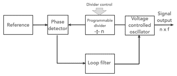
The phase locked loop consists of a number of circuit blocks - a reference, phase detector, voltage controlled oscillator and a filter. Essentially the loop compares the phase of the signals from the reference and the VCO and feeds back the output of the phase detector to the control terminal of the VCO via a filter.
The sense of the output from the phase detector is such that it tries to pull the VCO frequency towards that of the reference. Eventually a point is reached where a steady voltage is applied to the VCO control terminal. This means that there is a steady phase difference between the reference and the VCO signals. As the phase difference is not changing, it means that the frequencies of the VCO and reference are exactly the same and the loop is in lock.
Note on the Phase Locked Loop, PLL:
The phase locked loop, PLL is a very useful RF building block. The PLL uses the concept of minimising the difference in phase between two signals: a reference signal and a local oscillator to replicate the reference signal frequency. Using this concept it is possible to use PLLs for many applications from frequency synthesizers to FM demodulators, and signal reconstitution.
Read more about Phase Locked Loop, PLL
To develop the phase locked loop into a digital PLL frequency synthesizer, a digital divider is placed between the VCO and the phase detector to divide the VCO frequency down.
The way in which a digital divider is added to the frequency synthesizer loop can be seen in the diagram below.
Programmable dividers or counters are used in many areas of electronics, including many radio frequency applications. They take in a pulse train like that below, and give out a slower train.
In a divide by two circuit only one pulse is given out for every two that are fed in and so forth. Some are fixed, having only one division ratio. Others are programmable and digital or logic information can be fed into them to set the division ratio.

In this case the division ratio is 3
When the divider is added into the circuit the phase locked loop, PLL, still tries to reduce the phase difference between the two signals entering the phase comparator. Again when the circuit is in lock both signals entering the comparator are exactly the same in frequency. For this to be true the voltage controlled oscillator must be running at a frequency equal to the phase comparison frequency times the division ratio.
It can be seen that if the division ratio is altered by one, then the voltage controlled oscillator will have to change to the next multiple of the reference frequency. This means that the step frequency of the synthesizer is equal to the frequency entering the comparator.
Frequency step increments
It can be seen from the operation of the basic digital frequency synthesizer, that the output frequency is 'n' times the phase comparison frequency, where 'n' is the division ration. Changing the division ratio by one is the smallest frequency change that can be made.
As a result it can be seen that the smallest frequency change that can be made is equal to the comparison frequency, i.e. the phase detector frequency. In the basic format for the digital frequency synthesizer, this is equal to the reference frequency.
Most synthesizers need to be able to step in much smaller increments if they are to be of any use. Often step sizes of 10 kHz, 12.5 kHz or 25 kHz are required where a radio operates within different set channels, and for radios that require continuous tuning, then step sizes of 100 Hz or less may be required.
To achieve this the comparison frequency must be reduced. This is usually accomplished by running the reference oscillator at a frequency of a MegaHertz or so, and then dividing this signal down to the required frequency using a fixed divider. In this way a low comparison frequency can be achieved.
The reference oscillators typically run at frequencies of a few MHz, often 5 MHz or 10 MHz because at these frequencies the performance is better and the size of the crystal is achievable.

Using a frequency divider after the reference generator enables the low phase comparison frequency while allowing the reference oscillator to run at a convenient frequency, often around 10 MHz.
When developing a digital synthesizer with a low reference frequency, it means that the programmable divider has a much higher division ratio as it needs to divide down from the output frequency to the lower comparison frequency. This can lead to issues with delays through the divider as well as high phase noise and the like.
Digital PLL frequency accuracy & stability
One of the issues with oscillators such as free running variable frequency oscillators is that they are not very stable and also they are difficult to calibrate. Being an analogue circuit they are prone to drift and may also need an additional calibrator to ensure they are on the right frequency. In fact older communications radios using LC tuned free running variable frequency oscillators in the RF design normally incorporated a crystal calibrator to provide a check of the frequency calibration.
Fortunately, using a digital PLL frequency synthesizer the frequency is determined by the crystal oscillator. This means that the performance of the crystal oscillator will determine the frequency stability of the whole synthesizer.
In fact the frequency stability in terms of frequency drift in parts per million will be that of the final output.
Obviously the absolute frequency stability in terms of drift in terms of Hz / °C will be multiplied by the overall multiplication ratio of the loop. In other words if the reference oscillator is running at 10MHz and the final output is at 150 MHz and any absolute figures for drift will be multiplied by 150 / 10 = 15. However in terms of drift in terms of parts per million this will remain the same as this figure is a ratio.
Example of a digital PLL frequency synthesizer
It often helps to give some real figures to help understand the operation of an RF circuit design or other technique.
To give an example, the reference oscillator might be operating at a frequency of 1 MHz. To obtain the best stability and overall performance a crystal oscillator is required as the reference and the optimum performance is obtained from crystals operating in this region - 1 MHz, 5 MHz, 10 MHz are all common frequencies for reference oscillators.
For a synthesizer step size of 12.5 kHz which is widely used for narrow band FM handie talkies or base stations for radio communications. To obtain a phase comparison frequency of 12.5 kHz the RF circuit design needs to incorporate a digital divider with a fixed division ratio of 80 ( 1 MHz divided by 80 = 12.5 kHz.
If the synthesizer output is to operate between 144 and 146 MHz then the programmable divider must be able to provide a division ratio from 11520 to 11680.
This is only an example and any suitable figures could be used to provide the required frequency range and step size. The main requirement is to not make the division ratio so large that loop stability or phase noise becomes an issue.
Digital PLL synthesizers and phase noise
One of the issues with single loop digital PLL frequency synthesizers is that phase noise can easily become an issue.

Many early VHF / UHF transceivers suffered badly from issues of phase noise with poor receiver performance and also the transmission of high levels of phase noise extended out either side of the carrier.
It is important to address any issues associated with phase noise as part of the initial RF circuit design for the synthesizer.
Fortunately it is possible to design the circuit to reduce the level of phase noise, although using just a single loop, there is only so much that can be achieved.
Digital PLL frequency synthesizers are one of the most popular forms of frequency synthesiser. The technology is well established and there are very many synthesize ICs available. This makes the RF circuit design comparatively easy. In addition to this, digital PLL synthesizers are also included in many larger ICs designed for specific function - Bluetooth, Wi-Fi, and many more.
Over all the digital PLL synthesizer is well embedded in the RF circuit design culture and is a very popular electronic circuit design block.
More Essential Radio Topics:
Radio Signals
Modulation types & techniques
Amplitude modulation
Frequency modulation
OFDM
RF mixing
Phase locked loops
Frequency synthesizers
Passive intermodulation
RF attenuators
RF filters
RF circulator
Radio receiver types
Superhet radio
Receiver selectivity
Receiver sensitivity
Receiver strong signal handling
Receiver dynamic range
Return to Radio topics menu . . .