
Foster Seeley Discriminator: FM detector / demodulator
The Foster Seeley FM discriminator, detector or demodulator enabled audio to be recovered from frequency modulated signals using a relatively simple circuit .
Frequency Modulation Tutorial Includes:
Frequency modulation, FM
Modulation index & deviation ratio
FM sidebands, bandwidth
FM demodulation
FM slope detector
FM ratio detector
Foster Seeley detector
PLL FM demodulator
Quadrature demodulator
MSK
GMSK
Modulation formats:
Modulation types & techniques
Amplitude modulation
Phase modulation
Quadrature amplitude modulation
The Foster Seeley circuit is probably most commonly called the Foster Seeley discriminator. This is really a hang-over from early days of FM, and today the terms detector or probably better demodulator would probably be used.
The Foster Seeley discriminator circuit is characterised by the transformer, choke and diodes used within the circuit that forms the basis of its operation.
This FM demodulator circuit was invented by Dudley E. Foster and Stuart William Seeley in 1936. Although it was originally intended as a circuit to provide automatic frequency control, it was more widely used as an FM demodulator, whilst also being able to provide a voltage for automatic frequency control.
The Foster Seeley circuit was widely used until the 1970s when ICs using other techniques that were more easily integrated became widely available.
The circuit was widely used for all forms of radio communications applications from broadcasting to two way radio communications.
Foster-Seeley FM discriminator basics
The Foster Seeley detector or as it is sometimes described the Foster Seeley discriminator is quite similar to the ratio detector at a first look. It has an RF transformer and a pair of diodes, but there is no third winding - instead a choke is used.
In many respects the Foster Seeley FM demodulator resembles the circuit of a full wave bridge rectifier - the format that uses a centre tapped transformer, but additional components are added to give it a frequency sensitive aspect.

The basic operation of the circuit can be explained by looking at the instances when the instantaneous input equals the carrier frequency, the two halves of the tuned transformer circuit produce the same rectified voltage and the output is zero.
If the frequency of the input changes, the balance between the two halves of the transformer secondary changes, and the result is a voltage proportional to the frequency deviation of the carrier.
Looking in more detail at the circuit, the Foster-Seeley circuit operates using a phase difference between signals. To obtain the different phased signals a connection is made to the primary side of the transformer using a capacitor, and this is taken to the centre tap of the transformer. This gives a signal that is 90° out of phase.
When an un-modulated carrier is applied at the centre frequency, both diodes conduct, to produce equal and opposite voltages across their respective load resistors. These voltages cancel each one another out at the output so that no voltage is present.
As the carrier moves off to one side of the centre frequency the balance condition is destroyed, and one diode conducts more than the other. This results in the voltage across one of the resistors being larger than the other, and a resulting voltage at the output corresponding to the modulation on the incoming signal.
The choke is required in the circuit to ensure that no RF signals appear at the output. The capacitors C1 and C2 provide a similar filtering function.
Both the ratio detector and Foster-Seeley detectors are expensive to manufacture. Any wound components like the RF transformers are expensive to manufacture when compared with integrated circuits produced in vast numbers. As a result the Foster Seeley discriminator as well as the ratio detector circuits are rarely used in modern radio receivers as FM demodulators.
Foster Seeley circuit for frequency control
Prior to the introduction of very stable local oscillators within superhet radios - the universal format for radios receiving FM, local oscillators had a tendency to drift. Drift was a major factor in domestic radio receivers, although it was present in all radios.
When receiving FM signals the drift meant that the incoming FM signal might drift away from being at the centre of the FM detector slope onto the non-linear portions. This meant that the signal would become distorted.
To overcome this, radio receivers would incorporate a facility known as automatic frequency control was implemented. Using this, the DC offset from the FM demodulator is used to tune the receiver local oscillator to bring it back on frequency.

A DC offset is produced when the centre frequency of the carrier is not on the centre of the demodulator curve. By filtering off the audio, only a DC component remains.
Typically a long time constant RC combination is used to achieve this. The time constant of this RC network can be quite long as the drift of the oscillator occurs gradually over a period of seconds, and it must also be longer than that of the lowest frequency of the audio.
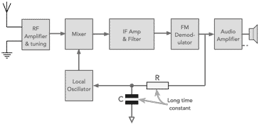
The filtered voltage is applied to a varactor diode within the local oscillator such that it causes the local oscillator to remain on tune for the FM signal being received. In this way the receiver can operate so that the signal being received is demodulated within the linear region of the FM demodulator.
Essentially the effect of the AFC circuitry is to create a form of negative feedback loop that seeks to keep the centre of the FM signal at the centre of the FM demodulation S curve. It is essentially a frequency locked loop.
Most radios used for FM reception that have free running local oscillators incorporate an automatic frequency control, AFC circuit. It uses only a few components and it provides for a significant improvement in the performance of the receiver, enabling the FM signal to be demodulated with minimum distortion despite the drift of the local oscillator signal.
Prior to the widespread introduction of frequency synthesizers, AFC was not always used in radios such as walkie talkies and handhelds radios aimed at for two way radio communications applications as they tended to use crystal controlled oscillators and these did not drift to any major degree. Hence there was less requirement for an AFC.
Foster-Seeley detector advantages & disadvantages
As with any circuit there are a number of advantages and disadvantages to be considered when choosing between the various techniques available for FM demodulation.
Advantages of Foster-Seeley FM discriminator:
- Offers good level of performance and reasonable linearity.
- Simple to construct using discrete components.
- Provides higher output than the ratio detector
- Provides a more linear output, i.e. lower distortion than the ratio detector
Disadvantages of Foster-Seeley FM discriminator:
- Does not easily lend itself to being incorporated within an integrated circuit.
- High cost of transformer.
- Narrower bandwidth than the ratio detector
- The circuit is sensitive to both frequency and amplitude and therefore needs a limiter before it to remove amplitude variations and hence amplitude noise.
Like all circuits, the Foster Seeley FM detector has its own advantages and disadvantages. By understanding these it is possible to mitigate the disadvantages and utilise the advantages to give the best performance.
As a result of its advantages and disadvantages the Foster Seeley detector or discriminator is not widely used these days. Its main use was within radios constructed using discrete components whether for broadcast, or radio communications including walkie talkies / hand held radio for two way radio communications applications.
More Essential Radio Topics:
Radio Signals
Modulation types & techniques
Amplitude modulation
Frequency modulation
OFDM
RF mixing
Phase locked loops
Frequency synthesizers
Passive intermodulation
RF attenuators
RF filters
RF circulator
Radio receiver types
Superhet radio
Receiver selectivity
Receiver sensitivity
Receiver strong signal handling
Receiver dynamic range
Return to Radio topics menu . . .

