
Doherty Power Amplifier Design
Doherty amplifier RF circuit design needs to ensure the performance of both RF amplifiers is optimised along with the biasing, splitter, feed, matching and combination to ensure the most efficiency operation
Doherty Amplifier Includes:
Doherty amplifier
Design techniques
Doherty amplifiers are used in many RF power applications. Even though reference designs may often be used, an understanding of their operation and the RF circuit design challenges needs to be understood so that the tailored design meets its requirements.
Doherty amplifier design requires the two amplifiers used to operate efficiently and the split, matching combination and phasing to be all optimised to achieve the required result and improved efficiency.
The RF circuit design of a Doherty amplifier from scratch is an involved process requiring an in-depth knowledge and understanding the of the technique as well as the performance of each element of the amplifier.
Doherty amplifier operation
Before looking at the RF circuit design of the Doherty amplifier, it is necessary to look at the basic operation of the RF amplifier.
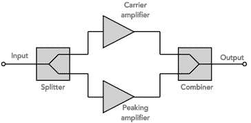
The RF circuit design of a Doherty amplifier uses a main or carrier amplifier that is typically biased for Class AB operation. A second active device, typically named the auxiliary or peaking amplifier that is normally biased for Class C operation.
The signal enters the overall Doherty power amplifier and is presented to a splitter. This creates two signals that are phase shifted by 90° with respect to each other. The reason for this is that inductive splitters are used to reduce the power loss and these create a 90° phase shift between the two signals.
One output is presented to the carrier amplifier. This is designed to accommodate the lower power levels encountered around the average power level. This is designed to provide optimum efficiency for these power levels.

The signal is also presented to the peaking amplifier. This is biased so that it only started operating when large peaks are present that the carrier amplifier would not be able to accommodate on its own. Being a higher power amplifier, this would not provide high levels of efficiency for the lower power levels and therefore it only operates when higher power levels are present. In this way optimum efficiency is obtained over the power range.
One the signal has passed through the RF amplifier circuits themselves, the outputs are combined using a reverse of the splitter circuit. As this also has a 90° phase shift, this is used to counteract the phase shift at the input. As a result, signals from the two amplifier sections remain in phase.
Doherty amplifier operation: detail
The basic Doherty amplifier theory requires that the signals between the two halves are matched in phase so that the combination occurs in a way that both signals add together to provide the required output.
The power split at the input of the Doherty amplifier is relatively straightforward. The power split is accomplished using a quadrature splitter: typical topologies include the Lange or branch-line techniques.
The input operates like a balanced amplifier. It has the same feature where the reflection coefficients of mismatched amplifiers are reduced if the reflection coefficients are equal in amplitude and phase. The reflected waves dissipate in the load terminating the isolated port of the coupler.

The combination of the two amplifier signals at the output presents more issues. The two signals are out of phase by 90° and using a quarter wave line in the output circuit of the peaking amplifier brings them back into phase with each other again.
The impedances also need to be accurately matched to ensure the efficiency is maintained. The impedance of both RF amplifiers is Z0/2. This is stepped up to Z0 by a quarter wave transformer.
This seems simple, but the amplifiers are operating in a non-linear fashion in view of the fact the peaking amplifier only operates on peaks. During operation, the response of one amplifier actively load-pulls the other, as they are not isolated. This means that nonlinear analysis needs to be undertaken to complete the design.
It is possible to operate both RF amplifier sections in the same class, but use an adaptive biasing scheme to turn on the peaking amplifier when it is needed - often the carrier amplifier operates in class A or AB and the peaking amplifier in class C. Another approach is to utilise unequal-sized devices or it is possible to use an unequal-split power divider on the input.
Doherty amplifier design issues
During the RF circuit design process developers aim to provide the optimum performance under the expected conditions as efficiently as possible. However these goals cannot all be achieved at the same time and significant trade-offs need to be made.
To achieve the best overall performance it is necessary to find an a parameter set and operating point that provides a good compromise of the sensitivity of the design to frequency, phase and level variations. This requires that an in-depth knowledge of the characteristics of both amplifiers and the splitters and combiners is known.
Often the RF circuit design technique involves using the manufacturers reference designs which can then be fine-tuned. This often makes it difficult to fully optimise the design for the specific applications explore as only minor design changes are normally made to the reference design.
It can be seen that RF circuit design of a Doherty amplifier presents many interesting and challenging aspects if the overall amplifier is to work well:
- Phase maintenance: In theory the phase of the signals through the different paths should be that same at the combination point. The RF splitter introduces a 90° phase shift on one leg, and this can be cancelled at the combination stage as a 90° shift also occurs in the combiner and this can be added in the other leg. However amplifiers will introduce a phase shift and this may not be equally match as one is designed to handle the lower power levels and the other for the peaks. This means that their characteristics will be different (in the asymmetric case).
- Impedance matching: Ensuring that the impedance of both RF amplifiers is sufficiently maintained over the operating range can present issues in some designs. Optimising the different electronic components to achieve this can be difficult.
- Linearity maintenance: It is found that kinks or disturbances in the linearity of the amplifier can occur as the peaking amplifier starts to operate. This adds distortion to the waveform being amplified. Care is also required to ensure linearity over the whole of the operating range.
- Bandwidth: Typically Doherty amplifier designs are limited in terms of their bandwidth. Some of the electronic components including the splitters and combiners are limited in their bandwidth, and outside this their phase shift varies significantly, impairing the performance of the overall amplifier design.
In most instances reference designs for Doherty amplifiers are used and this often only requires small adjustments to be made to the values of some of the electronic components. Typically these reference designs are provided for some of the most common end uses, and therefore little needs to be done to the design.
Normally the reference RF design, including the PCB layout may be the incorporated into the overall printed circuit board layout, but with minor changes to some electronic component values. Despite this, care still needs to be taken to ensure that the final RF circuit design operates as required. Even minor changes to the printed circuit board layout can have a significant impact on the performance.
Although the Doherty amplifier has its RF circuit design design challenges, it has established a firm place in applications such as the final power output stages for cellular base station, and other wireless communications and radio communications applications.
Despite the difficulties in the design process, when the RF design has been optimised, the Doherty amplifier is able to provide significant improvements in performance in efficiency and other areas as well. These can be very useful when developing new cellular base stations, wireless communications systems and also radio communications systems of various types
More Essential Radio Topics:
Radio Signals
Modulation types & techniques
Amplitude modulation
Frequency modulation
OFDM
RF mixing
Phase locked loops
Frequency synthesizers
Passive intermodulation
RF attenuators
RF filters
RF circulator
Radio receiver types
Superhet radio
Receiver selectivity
Receiver sensitivity
Receiver strong signal handling
Receiver dynamic range
Return to Radio topics menu . . .


