
How Does a Thyristor / SCR Work? - thyristor operation
A thyristor / SCR can be considered as two back to back transistors to explain its operation and how it works.
Triac, Diac, SCR Tutorial Includes:
Thyristor basics
Thyristor device structure
Thyristor operation
Gate turn off thyristor, GTO
Thyristor specifications
What is a triac
Triac specifications
Diac overview
When designing and using thyristor or SCR circuits it helps to understand how the thyristor works.
Essentially the operation of the thyristor / SCR can be explained in terms of a latching switch. Once tuned on by a current at the gate, it requires the voltage across the cathode and anode to be removed before it stops conducting.
Thyristor operation: the basics
In operation, the thyristor / SCR has three states in which it can be at any given time:
- Reverse blocking: In this mode or state the thyristor blocks the current in the same way as that of a reverse biased diode. The thyristor / SCR can only conduct in one direction and blocks in the reverse direction.
- Forward blocking: In this mode or state the thyristor operation is such that it blocks forward current conduction that would normally be carried by a forward biased diode. In this state the thyristor / SCR is not in its “turn-on” state as the gate has not fired.
- Forward conducting: In this mode the thyristor / SCR has been triggered into conduction by a current on the gate. It will remain conducting regardless of the state of the gate. Current only needs to be applied to the gate to fire the thyristor / SCR, and it will remain conducting. The device will stop conducting when the forward current drops below a threshold value known as the "holding current."
The thyristor consists of four semiconductor regions: P N P N. The outer P region forms the anode, and the outer n region forms the cathode as shown below.

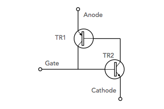
To look at how a thyristor works it is helpful to use a simplified equivalent circuit. This consists of two back to back transistors as shown below.
The transistor with its emitter connected to the cathode of the thyristor is an NPN device whereas the transistor with its emitter connected to the anode of the SCR is a PNP variety. The gate is connected to the base of the NPN transistor.

This arrangement forms a positive feedback loop within the thyristor. The output of one transistor fed to the input of the second. In turn the output of the second transistor is fed back to the input of the first. As a result it can be seen that the total current gain of the device exceeds one. This means that when a current starts to flow, it quickly builds up until both transistors are fully turned on or saturated.
When a voltage is applied across a thyristor no current flows because neither transistor is conducting. As a result there is no complete path across the device. If a small current is passed through the gate electrode, this will turn "on" the transistor TR2. When this occurs it will cause the collector of TR2 to fall towards the voltage on the emitter, i.e. the cathode of the whole device. When this occurs it will cause current to flow through the base of TR1 and turn this transistor "on". Again this will now try to pull the voltage on the collector of TR1 towards its emitter voltage. This will cause current to flow in the emitter of TR2, causing its "on" state to be maintained. In this way it only requires a small trigger pulse on the gate to turn the thyristor on. Once switched on, the thyristor can only be turned off by removing the supply voltage.
The operation of the thyristor considered in this way is relatively straightforward to understand.
More Electronic Components:
Batteries
Capacitors
Connectors
Diodes
FET
Inductors
Memory types
Phototransistor
Quartz crystals
Relays
Resistors
RF connectors
Switches
Surface mount technology
Thyristor
Transformers
Transistor
Unijunction
Valves / Tubes
Return to Components menu . . .

