
What is a DIAC: Operation, Applications, Specifications, Circuits
Understand exactly what a DIAC is, its structure, characteristics, specifications and how it can be used to provide improved performance and defined switching points for a triac.
Triac, Diac, SCR Tutorial Includes:
Thyristor basics
Thyristor device structure
Thyristor operation
Gate turn off thyristor, GTO
Thyristor specifications
What is a triac
Triac specifications
Diac overview
A DIAC is a full-wave or bi-directional semiconductor switch that can be turned on in both forward and reverse polarities.
The name DIAC comes from the words DIode for lternating Current. This name gives an insight into its operation and applications within electronic circuit design.
The DIAC is an electronics component that is widely used to assist even triggering of a TRIAC when used in AC switches and as a result they are often found in light dimmers such as those used in domestic lighting.
These electronic components are also widely used in starter circuits for fluorescent lamps, and they can also be used for various timing and oscillator functions as well as providing some protection against transients for some circuits.
Although the term is not often seen, DIACs may also be called symmetrical trigger diodes - a term resulting from the symmetry of their characteristic curve.
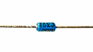
DIACs come in a variety of formats. As discrete components they may be contained in small leaded packages, they can be obtained in surface mount packages, in large packages that bolt to a chassis, or a variety of other packages. As they are often used as a DIAC TRIAC combination, they are often integrated into the same die as a TRIAC.
Video: Understanding DIACs: DIode for Alternating Current
DIAC symbol
The DIAC symbol used to depict this electronic component in circuit diagrams can be remembered as a combination of what may appear to be two diodes in parallel with each other but connected in opposite directions.

Owing to the fact that DIACs are bi-direction devices the terminals cannot be labelled as anode and cathode as they are for a diode. Instead they may be labelled as A1 and A2 or MT1 and MT2, where MT stands for "Main Terminal."
DIAC operation
Electronic circuit designs incorporating DIACs use the fact that a DIAC only conducts current only after a certain breakdown voltage has been exceeded. This is marked as VBO on the diagram.
The actual breakdown voltage will depend upon a variety of factors in its fabrication, but it will be given in the specification for the particular component type.
When the DIAC breakdown voltage occurs, the resistance of the component decreases abruptly and this leads to a sharp decrease in the voltage drop across the DIAC to VF.
There is a corresponding increase in current. This can be clearly seen on the I/V characteristic for the device below.
The DIAC will remain in its conducing state until the current flow through it drops below a particular value known as the holding current. When the current falls below the holding current, the DIAC switches back to its high resistance, or non-conducting state.

DIACs are widely used in AC applications and it is found that the device is "reset" to its non-conducting state, each time the voltage on the cycle falls so that the current falls below the holding current.
As the behaviour of the device is approximately equal in both directions, it can provide a method of providing equal switching for both halves of an AC cycle, e.g. for TRIACs.
Most DIACs have a breakdown voltage of around 30 volts, although the exact specifications will depend upon the particular type of device.
Interestingly their behaviour is somewhat similar to that of a neon lamp, although they offer a far more precise switch on voltage and thereby provide a far better degree of switching equalisation.
DIAC structure
The DIAC can be fabricated as either a three layer or a five layer structure - the difference between the two devices is relatively small in practice.
In the three layer structure the switching occurs when the junction that is reverse biased experiences reverse breakdown. The three layer version of the device is the more common and can have a break-over voltage of around 30 V. Operation is almost symmetrical owing to the symmetry of the device.
Although the structure may appear to be similar to that of a bipolar transistor, the actual fabrication and layers, etc are rather different. The central region, for example is much thicker.

A five layer DIAC structure is also available. This does not act in quite the same manner, although it produces an I-V curve that is very similar to the three layer version.
This structure can be considered as two break-over diodes connected back to back.

In terms of its operation, when the top terminal is more positive with respect to bottom one on the diagram, the current does not flows through the corresponding N-layer but flows the path consisting of P2, N2, P1, N1. When potential is reversed the current flows through the path of the regions P1, N2, P2, N3.
For most applications a three layer version of the DIAC is used. It provides sufficient improvement in switching characteristics. For some applications the five layer device may be used.
DIAC specifications
When selecting a DIAC for a circuit design, it is necessary to have a good understanding of the relevant specifications.
There are several parameters that are more specific to DIACs and it is necessary to have a good understanding of what they are and how they affect the circuit.
Breakover voltage, VBO: The breakover voltage is the voltage at which the DIAC switches from its blocking state to its conducting state. It is normally specified for both the positive and negative directions.
Breakover voltage and and also the breakover current are the two most important DIAC specifications for most circuit situations because they determine the operating conditions.
For a circuit design, tThe breakover voltage should be high enough to prevent the DIAC from triggering accidentally, but low enough to be triggered reliably by the desired trigger signal. As always there can be a bit of a balance in determining the right breakover voltage, and then in selecting a component that has the nearest breakover voltage to the desired value.
It should be remembered that the breakover voltage is temperature dependent, often varying by around ±5% over the operating temperature range.
Breakover current, IBO: The breakover current is the minimum current required to trigger the DIAC. It is typically specified for both the positive and negative directions.
As with the breakover voltage, the breakover current should be low enough to be triggered by the available trigger signal, but high enough to prevent the DIAC from being damaged by excessive current.
On-state voltage, VTO: This is the voltage drop across the DIAC when it is in its conducting state. It is typically specified for a given on-state current.
On-state current, IT: This is the maximum current that the DIAC can conduct in its on-state. It is typically specified for a given on-state voltage. As with any specification defining the maximum current, the device should be operated well within its maximum rating
Power dissipation, PD: This is the maximum power that the DIAC can dissipate in its on-state. It is typically specified for a given on-state voltage and current, and again the device should be operated well within its maximum rating to improve the reliability.
Operating junction temperature range °C: This is the temperature range for the actual semiconductor in the device over which the device can safely operate. Very low temperatures will often reduce the activity of the semiconductors themselves and will reduce performance. If it is too high then the device temperates can lead to a considerable lowering of reliability.
It should be remembered that the junction temperature wil be in excess of the ambient temperature within the equipment. Often a figure is given within the datasheet to enable the junction temperature to be calculated from a knowledge of the circuit conditions and the ambient temperature.
Breakover Voltage Symmetry This is a measure of how the device performs over both halves of an AC waveform. If the voltage symmetry of the DIAC is not good, it can cause the circuit to behave differently for the positive and negative half-cycles of the AC waveform. This can lead to distortion of the signal and in extreme conditions, it could even cause the circuit to malfunction.
When selecting a DIAC for a particular application, it is important to consider all of the relevant specifications to ensure that the device will meet the performance and reliability requirements of the circuit.
DIAC applications
There are many ways in which DIACs are used, some are what may be termed the more standard uses, whereas others may be cosnidered as being more specialist.
• Use in conjunction with TRIACs
One of the major uses of DIACs within electronic circuit designs that utilise TRIACs. TRIACs do not fire symmetrically as a result of slight differences between the two halves of the device.
The non-symmetrical firing and resulting waveforms give rise to the generation of unwanted harmonics – the less symmetrical the waveform the greater the level of harmonic generation.

To resolve the issues resulting from the non-symmetrical operation, a DIAC is often placed in series with the gate. This device helps make the switching more even for both halves of the cycle. This results from the fact that the DIAC switching characteristic is far more even than that of the TRIAC.
Since the DIAC prevents any gate current flowing until the trigger voltage has reached a certain voltage in either direction, this makes the firing point of the TRIAC more even in both directions. In view of their usefulness, DIACs may often be built into the gate terminal of a TRIAC.
While the use of a DIAC improves the performance of the TRIAC, it is still not perfect and as a result TRIACs tend to be used within small current or power switching electronic circuit designs as some non-symmetry remains with the resulting harmonics and other issues are still present. These would be far more important within high current circuits and therefore two thyristors are generally used instead.
The use of two thyristors provides a far more satisfactory high current solution than a TRIAC, but at the cost of additional electronic components. The TRIAC is ideal for small power circuit designs because it reduces the electronic component count, the overall size and cost. It is for this reason that they are widely used in light dimmers where size and cost are very important parameters.
• Use in telephone PSTN shared lines
As a result of the Electronics Notes video, one of the comments came from a former telecommunications engineer who commented about the way in which DIACs were used to enable shared lines to work. Although they are rarely used these days, they were relatively common before the mid 1960s in some areas of the globe.
He commented:
When I was a telephone engineer, I used DIACs as a privacy device where multiple telephones were on the same PSTN circuit. Put one in the line path on each telephone.
The line voltage across the diac wil be around 50v so you get dial tone when you pick up, the line voltage falls to around 12v but the diac continues to conduct.
Anyone else picking up a phone on that circuit gets a dead line because the 12v is below the break over voltage. Simple single component privacy.
Diac circuits
The diac is most commonly used with a triac to even out the firing on both sides of the cycle to improve several aspects of the performance as mentioned above.
There are many examples of diacs being used in circuits, especially with triacs.
The basic circuit is shown below and it shows how the diac is placed in series with the gate of the triac to provide a more even degree of switching on either side of te cycle.

One of the issues with triac switching is that high levels of harmonics can be geenrated a these can be sent along the power line where they can be conducted or radiated.
As a result a filter is often added, often using capacitors and inductors. One simple example of a simple CR filter is shown below. Howdver the switching action of the diac remains the same.

These are just two of the basic diac circuits, showing the method in which these devices can be used.
Example of DB3 DIAC specifications
It is sometimes useful to be able to see the specification for a typical DIAC. We have chosen a DB3 DIAC as this is a very popular type and below are the specification parameters for this device.
| Highlight specifications parameters for a DB3 leaded DIAC |
||
|---|---|---|
| Parameter | Specification Details | |
| Breakover voltage range | 28 - 36V | |
| Maximum breakover current | 50µA | |
| Maximum rise time | 2µs | |
| Operating junction temperature range | -40°C to +125°C | |
| Repetitive peak on-state current | 2A @ 120Hz | |
These example parameters and specifications for the popular DB3 DIAC give an indication of what the typical performance for a DIABC may be.
DIACs are a widely used electronic component. The chief application of DIACs is for use in conjunction with TRIACs to equalise their switching characteristics. By equalising the switching characteristics of these TRIACs, the level of harmonics generated when switching AC signals can be reduced.
Despite this, for large applications, two thyristors are generally used rather than a single triac. Nevertheless the DIAC / TRIAC combination is very useful for lower power applications including light dimmers, etc.
More Electronic Components:
Batteries
Capacitors
Connectors
Diodes
FET
Inductors
Memory types
Phototransistor
Quartz crystals
Relays
Resistors
RF connectors
Switches
Surface mount technology
Thyristor
Transformers
Transistor
Unijunction
Valves / Tubes
Return to Components menu . . .


