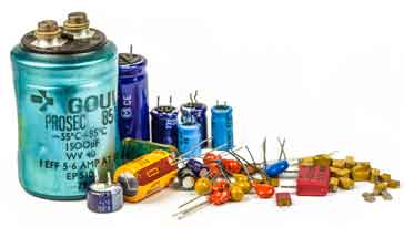
Capacitors have a large number of markings and codes indicating their value, tolerance, etc - uncover the mysteries in this informative guide to reveal this key information.
Capacitors have a variety of marking codes on them. These markings and codes indicate various properties for the capacitors and it is essential to understand them in order to select the required type.
Today most capacitors are marked with alphanumeric codes but older capacitors may be seen that have colour codes. These capacitor colour codes are less common than in previous years, but some may still be seen.
Different types of capacitors have different marking codes and schemes
The capacitor marking codes vary in their format according to whether the component is a surface mount device or whether it is leaded device, as well as the capacitor dielectric.
Size also plays a major part in determining how the capacitor is marked – small components must use abbreviated coding systems, whereas larger capacitors such as aluminium electrolytic varieties may write the relevant parameters on the case in full.
In fact the size of surface mount capacitors often means that they do not have value markings on them - during manufacture, the reels of the various electronic components used are marked, but the individual devices are not. Virtually all leaded capacitors are marked.
Capacitor marking codes: the basics
Capacitors are marked in many different ways. There are a number of basic marking systems that are used and different capacitor types and different manufacturers use these as needed and best fits the particular product.
Marking of the various electronic components and in this case capacitors makes servicing and repair much easier. That said the reliability of modern electronic printed circuit boards and equipment these days, along with their complexity often means that repair is often only done by the manufacturer and replacement boards or assemblies are used.
However many electronic components are still marked and this can also help in the electronic design process.
Some of the marking systems for electronic components and capacitors in particular have been standardised by the EIA - the Electronic Industry Alliance, and these provide commonality across the industry.
it is worth mentioning that on some occasions the abbreviation MFD is used on the casing of some larger electrolytic capacitors to denote µF and not a MegaFarad. This practice is being used less because there are some supercaps where the values extend into the Farad region, although not as far as a MegaFarad.
Some of the basic coding schemes for the different parameters are included below:
Non-coded markings: The most obvious way of marking a capacitor parameters are to directly mark them onto the case or encapsulation in some way. This method works best on larger capacitors where there is sufficient space for the markings.
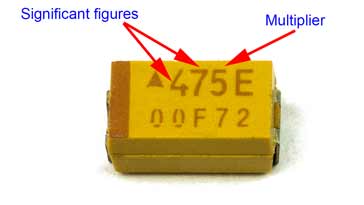
Abbreviated capacitor marking codes: Smaller capacitors may only have room for a few figures printed as a code for the value. This capacitor marking code uses three characters. It bears many similarities to the numeric code system adopted for some surface mount resistors. The first two figures refer to the significant figures of the capacitor value, and the third one acts as a multiplier. The value of the capacitor is denoted in picofarads for ceramic, film, and tantalum capacitors, but for aluminium electrolytic capacitors the value is denoted in microfarads.
Multiplier used on EIA Capacitor Marking Code
Third Figure
Multiplier
0
1
1
10
2
100
3
1000
4
10 000
5
100 000
6
1 000 000
For small values the letter R is used to denote a decimal point, e.g. 0R5 is 0.5, 1R0 is 1.0 and 2R2 is 2.2, etc..
This scheme is widely used with surface mount capacitors where space is very limited.
Colour code: Some older capacitors use a form of colour code. This type of capacitor marking is used less these days but may be seen on some older capacitors.
Tolerance codes: Some capacitors have a tolerance code. The code used is actually the same as that used with resistors as it utilises the EIA scheme:
EIA Tolerance Capacitor Marking Code
Letter code
Tolerance
Z
+80%, -20% - this is used with electrolytic capacitors where the minimum value is the main issue.
M
±20%
K
±10%
J
±5%
G
±2%
F
±1%
D
±0.5%
C
±0.25%
B
±0.1%
Capacitor working voltage codes: The working voltage for a capacitor is very important and therefore this parameter is often marked on capacitors and particularly in situations where there is space for alphanumeric coding. In many instances where the capacitor is small no voltage coding is provided and care must be taken when using a capacitor without any knowledge of its working voltage. Again the marking code uses the EIA scheme:
EIA Capacitor Voltage Codes
0G = 4.0VDC
1J = 63VDC
2D = 200VDC *
0L = 5.5VDC
0k = 80VDC
2P = 220VDC
0J= 6.3VDC *
2A = 100VDC *
2E = 250VDC *
1A = 10VDC *
2Q = 110VDC
2F = 315VDC
1C = 16VDC *
2B = 125VDC
2V = 350VDC
1E = 25VDC *
2C = 160VDC
2G + 400VDC *
1H = 50VDC *
2Z = 180VDC
2W = 240VDC
* These codes are preferred values
On some SMD electrolytic and tantalum capacitors a one character code is used. This occupies much less space and bears many similarities to the EIA system.
SMD Electrolytic Capacitor Voltage Codes
Letter
Voltage
e
2.5
G
4
J
6.3
A
10
C
16
D
20
E
25
V
35
H
50
Temperature coefficient codes
It is often necessary to mark a capacitor with a marking or code that indicates the temperature coefficient of the capacitor. These capacitor codes are standardised by EIA, but also some other generally used industry codes may also be seen in common use.
These codes are typically used for ceramic and other film type capacitors where the temperature coefficient may be of greater importance in the electronic circuit design.
The temperature coefficient is quoted in terms of parts per million per degree C; PPM/°C.
Common temperature coefficient markings
EIA
Industry
Temperature coefficient (ppm/°C)
C0G
NP0
0
S1G
N033
-33
U1G
N075
-75
P2G
N150
-150
S2H
N330
-330
U2J
N750
-750
P3K
N1500
-1500
Capacitor polarity markings
One important marking for polarised capacitors is the polarity. Great care must be taken to ensure the polarity markings are observed when inserting these capacitors into circuits otherwise damage to the component, and more importantly to the remainder of the circuit board can result.
Polarised capacitors effectively mean aluminium electrolytic and tantalum types as these are the commonly used forms of polarised capacitors.
Many recent capacitors are marked with the actual + and - signs and this makes it easy to determine the polarity of the capacitor.
Another format for electrolytic capacitor polarity markings is to use a stripe on the component. On an electrolytic capacitor the stripe indicates the negative lead.
Marking on an electrolytic capacitor - stripe indicates negative connection In this case the marking stripe also has a negative sign on it to reinforce the message.
If the capacitor is an axial version having leads at both ends of the package, the polarity marking stripe may be accompanied by an arrow that points to the negative lead.
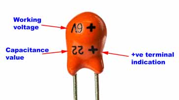
For leaded tantalum capacitors the polarity markings indicate the positive lead. A "+" sign is placed close to the positive lead. When new, a further polarity making may be used because it may be seen that the positive lead is longer than the negative one.
Leaded tantalum capacitor markings
Markings for different types of capacitor
Many larger capacitors like electrolytic capacitors, disc ceramics, and many film capacitors are large enough to have their markings printed on the case.
On a larger capacitors there is sufficient space to mark the value, the tolerance, working voltage, and often other data such as the ripple voltage.
There are a number of subtle differences in the capacitor codes and markings used for different types of leaded capacitors:
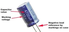
Electrolytic capacitor markings: Many leaded capacitors are quite large, although some are smaller. As such it is often possible to provide the complete value and details in a non-abbreviated format. However many smaller electrolytic capacitors need to have coded markings on them as there is insufficient space.
A typical marking may fall into the format 22µF 50V. The value and working voltage is obvious. The polarity is marked by a bar to indicate the negative terminal.
Leaded tantalum capacitor markings: Leaded tantalum capacitors generally have their values marked in microfarads, µF.
Typically the markings on a capacitor may give the figures like 22 and 6V. This indicates a 22µF capacitor with a maximum voltage of 6V.
Ceramic capacitor markings: Ceramic capacitors are generally smaller than types like electrolytic capacitors and therefore the markings need to be more concise. A variety of schemes may be used. Often the value may be given in picofarads. Sometimes figures such as 10n will be seen and this indicates a 10nF capacitor. Similarly n51 indicates a 0.51nF, or 510 pF capacitor, etc . .
SMD ceramic capacitor codes: Surface mount capacitors are often very small and do not have the space for markings. During manufacture the capacitors are loaded into a pick and place machine and there is no need for any markings.
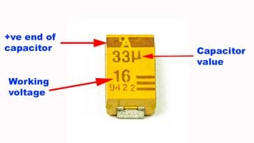
SMD tantalum capacitor markings: The most straightforward marking system for SMD tantalum capacitors is where the value is shown directly.
SMD tantalum capacitor markings Also note the bar indicating the +ve connection.
On the occasions that there is space for a marking or code, the simple three figure format like that shown below is often used, especially for capacitors such as ceramic formats. For the example of the capacitor code shown in the diagram, the two figures 47 indicate the significant figures and the 5 indicates the multiplier of 5, i.e. 100 000, i.e. 4.7µF.
SMD tantalum capacitor markings
In some cases the only marking shown on the capacitor may be a bar across one end indicating the polarity. This is particularly important because it is necessary to be able to check the polarity and to have a marking to identify the polarity of the capacitor. It is particularly important to have a capacitor polarity marking because reverse biasing tantalum capacitors leads to their destruction.
In general it is very easy to determine what the different capacitor codes and marking schemes mean. Although there appear to be many different coding schemes, they are normally very obvious, and if not their meaning is soon revealed when referring to a coding guide.
Fact of the day: It was on this day in 1965 that Moore\'s Law was first published in an article about the future of semiconductor components. At the time, Gordon Moore who wrote about it was the head of research and development for Fairchild Semiconductor and later he went on to co-found Intel.
Quote:Things may come to those who wait, but only the things left by those who hustle. Abraham Lincoln
Point to ponder: The first adding machine that was produced was the abacus. It was invented in China in the 9th Century.