Active Transistor Constant Current Source
The simplest form of current source is a resistor, but active current sources using transistors are able to provide a much more constant current, or controlled current.
Transistor Circuit Collection Include:
Transistor circuit collection
Common emitter
Emitter follower
Common base
Darlington pair
Sziklai pair
Current mirror
Long tailed pair
Constant current source
Capacitance multiplier
Two transistor amplifier
High pass filter
Switch circuits
Pulse generator
Schmitt trigger
One transistor relaxation oscillator
Transistor crystal-oscillator
See also:
Transistor circuit design
Active constant current sources are often used in electronic circuit design. Some constant current circuits can be made using a very few electronic components, but others providing better performance may use a few more.
The simplest constant current source uses a single electronic component: a resistor, but often the constant current sources use transistors, although FETs and where applicable, vacuum tunes of thermionic valves can be used as well.
It is possible to make an active constant current source using a single transistor and a couple of resistors, although more comprehensive designs are also available using a few additional electronic components.
What is a constant current source
The basic element is a current source and this is an element or block within a circuit whose function is to provide current - the main focus being on providing current rather than voltage.
The more useful item in terms of the provision of current is what is called a constant current source. This entity provides a specified level of current regardless of the impedance of the load into which it is driving the current.
A theoretical constant current source will be able to provide the constant current totally regardless of the impedance. Problems can occur when very high impedance levels or even open circuits are encountered because very high voltages might be required to reach the current levels required.
In view of this, real constant current sources have limitations placed upon the range of impedance levels where they can provide a constant current.
In terms of the I-V plot of the output of a constant current source, the characteristic is represented by a straight line.
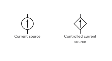
There are two types of constant current source:
Independent current source: For this form of current source, the current is independent of any variable in the circuit. In other words it produces a fixed current.
Controlled current source: This form of constant current device produces a level of current that can be controlled by an external factor, such as a control voltage, but it will be able to deliver the required level of current independent of the load.
Active current source applications
Current sources are needed in a number of different areas of electronics circuit design.
Current sources can be used to bias transistors and can also be used as active loads for high gain amplifier stages. They may also be used as the emitter sources for differential amplifiers - for example they may be used in the transistor long tailed pair.
They may also be used as wide voltage range pull-up links within power supplies and other wide voltage range circuits. If ordinary resistors were used then the current would vary considerably over the voltage range.
One common example of the use of current sources is to drive a Zener diode in a regulator circuit. Keeping the current constant regardless of the current taken by the series pass transistor in the circuit helps maintain a much better level of regulation.
Also stand-alone current sources are also needed in processes ranging including electrochemistry and electrophoresis.
In this way it can be seen that a constant current source is an important circuit block used in a wide variety of areas in electronic circuit design.
Simple resistor current source circuit
The simplest form of constant current circuit uses a single electronic component: a resistor. If the voltage of the source voltage is much higher than the voltage where the current is required, then the output current will be almost independent of the load.
For the perfect constant current source, the voltage source would have an infinite voltage and the resistor would have an infinite resistance.
For practical applications, the voltage and resistance should enable the current to be near enough constant over the range of load required.

For the circuit above, the current can be calculated very easily as it is approximately I = V / R because Vload (the voltage across the load) is much smaller than V (the voltage of the source).
This simple form of current source has many limitations:
- The high values of resistance needed dissipate power making circuits inefficient.
- High source voltages are needed and are not always easily available.
- Variations in load may cause some current variations if sufficiently high values of source voltage are not available.
In view of these limitations this simple constant current source is not widely used where a true constant current is needed.
To achieve better performance with a lower voltage source and with less power dissipation, although with a few extra electronic components, an active constant current circuit is more widely used, and provides better overall performance for most practical requirements.
Transistor active constant current source basics
The simple use of a transistor enables a far more effective current source to be made using just a few additional electronic components including a transistor, and some resistors and a few simple equations for the electronic circuit design.
The current source operates because of the fact that the collector current in a transistor circuit is Β times the base current. This is independent of the collector voltage, provided that there is sufficient voltage to drive the current through the load device in the collector.

In this circuit, the collector current is β times the base current. Normally β is large and therefore it can be assumed that the emitter current which is (β + 1) times the base current and the collector current which is β times the base current are the same.
In view of this it is a simple matter to design the circuit for a given current.
NB: This assumes the use of a silicon transistor as the base emitter drop is given as 0.6V
By setting the resistors R1 and R2 it is possible to set the base voltage. The emitter voltage will be 0.6 volts less, assuming a silicon transistor. By knowing the emitter voltage, it is possible to calculate the emitter current from a simple knowledge of Ohms law.
Simple stabilised active current source circuit
In order to remove any fluctuations in current arising from changes in supply voltage it is a simple matter to add some regulation to the basic circuit by changing a few of the electronic components. This is achieved by replacing R2 with a Zener or voltage reference diode.

The same equations apply as before, but the only difference is that the base voltage is held at a more constant level as a result of the presence of the Zener, voltage reference diode.
Active current source temperature dependence
One of the main disadvantages of the basic active current source is that it is dependent upon temperature to a degree. For many applications this may not be important, but where very tightly controlled conditions are needed, the temperature performance may be very important.
There are two main variations that occur:
- Variations of Vbe with respect to temperature The effects of the change in Vbe caused by temperature are approximately -2mV/°C. This results in a variation of Vce. It is possible to calculate an approximate relationship: ΔVbe approximately equals -0.0001ΔVce.
This can be minimised by choosing an emitter resistor value sufficiently large to ensure that emitter voltage changes of tens of millivolts will only be a small proportion of the overall emitter voltage. However care must be taken to ensure that there is still sufficient remaining voltage between the collector and the rail to drive the current through the load and take up any variations in supply voltage. - Variations of β with respect to temperature This may not be a major issue and any variations can be minimised by choosing a transistor with a high value of Β / Hfe. In this way the base current contribution to the emitter current is minimised and the variations reduced as far as possible.
Active current source circuits with good temperature stability
It is possible to design transistor active current source circuits where the inherent temperature stability is better than the simple circuits given above.
One of the simplest circuits is to employ one that uses both NPN and PNP transistors. In the circuit shown, the Vbe voltage drop changes in TR1 are compensated by those in TR2. It should be noted in this circuit that R3 is a pull up resistor for the collector of TR1 because the base of TR2 can sink current but not source it.

The circuits above all include transistors, but other active electronic components including FETs and even vacuum tubes / thermionic valves can also be used. When using other electronic components as the active device in a current source, the biasing arrangements and circuit need to account for the fact that both FETs and valves / tubes are voltage driven rather than current driven. Nevertheless they can still be used just as effectively.
Transistor active current sources are used in many areas, particularly within integrated circuits and some battery chargers. They enable a fixed, or controlled current to be supplied independent of the voltage (within limits) and as such they are very useful.
More Circuits & Circuit Design:
Op Amp basics
Op Amp circuits
Power supply circuits
Transistor design
Transistor Darlington
Transistor circuits
FET circuits
Circuit symbols
Return to Circuit Design menu . . .