
Parabolic Reflector Antenna Gain
Parabolic reflector antenna gain can be calculated from some simple formulas or equations, and the practical factors affecting the 'dish' antenna gain.
Log periodic antenna includes:
Parabolic / dish antenna basics
Parabolic antenna theory & equations
Parabolic antenna gain & directivity
Parabolic antenna feed systems
The gain is one of the key factors associated with the parabolic reflector antenna. It is an important factor for any antenna, especially when the viability of any radio communications link is being established, or for comparing the performance of various antennas.
The high level of gain is one of the main reasons why parabolic reflector antennas are used.
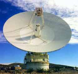
Image courtesy NASA
In fact the parabolic reflector antenna gain can be as high as 30 to 40 dB. These figures of gain are not easy to achieve using other forms of antenna.
At microwave frequencies where these antennas are normally used, they are able to produce very high levels of gain, and they offer a very convenient and robust structure that is able to withstand the rigours of external use. By contrast, many other types of antenna design are not practicable at these frequencies.
The one common feature of all these examples is the parabolic antenna gain, or parabolic dish gain. While the larger antennas have greater levels of parabolic antenna gain, the performance of all these antennas is of prime importance.
Factors affecting parabolic reflector antenna gain
As with any antenna, there are many different factors that affect the antenna gain, and naturally these have an impact on their overall design, cost, size, etc.
There are three main factors that affect the parabolic antenna gain:
- Diameter of reflecting surface The larger the diameter of the reflecting surface of the antenna the higher the parabolic reflector gain will be.
- Operational wavelength: The parabolic reflector antenna gain is dependent upon the reflector size in terms of wavelengths. Therefore if the same reflector is used on two different frequencies, the gain will be different. It is inversely proportional to the wavelength being used.
- Antenna efficiency: The efficiency of the antenna has a significant effect on the overall parabolic reflector gain. Typical figures are between 50 and 70%. The efficiency varies as a result of a number of different factors which are detailed below.
There are naturally some other factors, but these are the three main items that tend to be considered when designing or selecting an antenna for a particular radio communications or receiving application.
Parabolic reflector antenna gain
The gain of a parabolic reflector antenna, or any antenna, for that matter, is the ratio of the signal from the antenna in question when compared to that of a standard antenna. This ratio is normally expressed in decibels, dB.
the standard antenna can be an isotropic source - this is an imaginary antenna that radiates equally in all directions, or often a dipole antenna. The dipole antenna has a gain of 2.1dB at its maximum radiation over that of an isotropic source.
The parabolic antenna gain can easily be calculated from a knowledge of the diameter of the reflecting surface, the wavelength of the signal, and a knowledge or estimate of the efficiency of the antenna.
The parabolic reflector antenna gain is calculated as the gain over an isotropic source, i.e. relative to a source that radiates equally in all directions. This is a theoretical source that is used as the benchmark against which most antennas are compared. The gain is quoted in this manner is denoted as dBi.
The standard formula for the parabolic reflector antenna gain is:
Where:
G is the gain over an isotropic source in dB
k is the efficiency factor which is generally around 50% to 60%, i.e. 0.5 to 0.6
D is the diameter of the parabolic reflector in metres
λ is the wavelength of the signal in metres
From this it can be seen that very large gains can be achieved if sufficiently large reflectors are used. However when the antenna has a very large gain, the beamwidth is also very small and the antenna requires very careful control over its position. In professional systems electrical servo systems are used to provide very precise positioning.
It can be seen that the parabolic reflector gain can be of the order of 50dB for antennas that have a reflector diameter of a hundred wavelengths or more. This naturally leads to some very large sizes for antenas, even when the wavelengths being used are very small.
Whilst antennas of this level of gain would not be practicable for antenna types such as the Yagi, and many others, the parabolic reflector can be made very large in comparison to the wavelength and therefore it can achieve these enormous gain levels.
The parabolic reflector antenna is still capable of providing high levels of gain even for smaller reflector sizes of a few wavelengths, and this is why they are used for domestic satellite direct broadcast antennas.
Parabolic reflector gain efficiency
In the overall gain formula for the antenna, an efficiency factor is included. Typically this may be between 50 and 70% dependent upon the actual antenna.
The parabolic reflector antenna gain efficiency is dependent upon a variety of factors. These are all multiplied together to give the overall efficiency.
- Radiation efficiency, kr: The radiation efficiency is denoted as kr above. It is governed by the resistive or Ohmic losses within the antenna. It is controlled by the radiation efficiency of the element of the antenna that radiates the RF energy. For most antennas this is high and close to unity. Therefore the radiation efficiency does not have a major effect on the parabolic reflector antenna gain and is normally ignored.
- Spillover Efficiency ks: The spillover efficiency is denoted as ks above. Any energy that spills over the edge of the reflector surface will reduce the efficiency and hence the parabolic reflector antenna gain. In the ideal case, the reflector surface needs to be equally and fully illuminated and none should spill over the edge. In the real case this is not viable and some reduction in efficiency, and hence the antenna gain is experienced.
- Aperture Taper Efficiency kt: The aperture taper efficiency is denoted as kt above. It affects the antenna gain because the whole parabolic reflector needs to be properly illuminated for the optimum gain to be achieved. If parts of the surface are not optimally illuminated by the radiated energy from the radiator then the parabolic reflector gain will be reduced. The optimum performance is achieved when the centre is illuminated a little more than the edges.
- Surface Error: In order to provide the highest levels of parabolic reflector antenna gain, the surface must follow the parabolic contour as accurately as possible. Deviations from this will result in poor reflection accuracy. However it is possible to use a gauze for the reflector to reduce weight and wind resistance provided that the holes in the gauze or mesh are small in comparison with a wavelength. The width of the slots or holes in the reflective metal mesh must be less than λ/10.
- Aperture Blockage: The physical structure of the feed and other elements of the antenna often mask part of the reflector. This naturally reduces the efficiency and hence the antenna gain. This factor needs to be accommodated within the antenna gain calculation.
- Cross Polarization : As with any other antenna the polarisation of the transmitted and received signals must match otherwise there is a loss equal to the sine of the angle between the polarisations, assuming linear polarisation.
- Non-Single Point Feed: The focal point of the reflector is a single point. However all antennas have a finite size and therefore this will mean that the antenna extends outside the focal point of the reflector. The larger the radiating element with respect to the reflecting surface, the more of a problem this is and the larger impact it has on the antenna gain.
The term km is used to denote the various miscellaneous efficiency elements that are often more difficult to determine. These include those due to surface effort, cross polarisation, aperture blockage, and the non-single point feed.
Parabolic antenna beamwidth calculation
As the gain of the parabolic antenna, or any antenna, increases, so the beamwidth falls.
Normally the beamwidth is defined as the points where the power falls to half of the maximum, i.e. the -3dB points on a radiation pattern polar diagram.
It is possible to estimate the beamwidth reasonably accurately from the following formula.
Where:
G is the gain over an isotropic source in dB
D is the diameter of the parabolic reflector
λ is the wavelength of the signal
All dimensions must be in the same units for the calculation to be correct, e.g. both diameter and wavelength in metres, or both in feet, etc..
Optimising parabolic antenna gain
To provide the optimum illumination of the reflecting surface, the level of illumination should be greater in the centre than at the sides. It can be shown that the optimum situation occurs when the centre is around 10 to 11 dB greater than the illumination at the edge. Lower levels of edge illumination result in lower levels of side lobes.
The reflecting surface antenna forms a major part of the whole system. In many respects it is not as critical as may be thought at first. Often a wire mesh may be used. Provided that the pitch of the mesh is small compared to a wavelength it will be seen as a continuous surface by the radio signals. If a mesh is used then the wind resistance will be reduced, and this provides significant mechanical advantages.
The parabolic reflector antenna is able to provide a significant level of gain which can be put to good use, especially for microwave frequencies where the size of the antenna for a given level of gain becomes very managemable.
More Antenna & Propagation Topics:
EM waves
Radio propagation
Ionospheric propagation
Ground wave
Meteor scatter
Tropospheric propagation
Antenna basics
Cubical quad
Dipole
Discone
Ferrite rod
Log periodic antenna
Parabolic reflector antenna
Phased array antennas
Vertical antennas
Yagi
Antenna grounding
Installation guidelines
TV antennas
Coax cable
Waveguide
VSWR
Antenna baluns
MIMO
Return to Antennas & Propagation menu . . .


