Folded Dipole Antenna / Aerial
Notes and summary about the folded dipole antenna, folded dipole impedance, unequal conductor folded dipoles, and multi-wire folded dipoles.
Dipole Antennas Include:
Dipole antenna basics
Current & voltage
Half wave dipole
Folded dipole
Short dipole
Doublet
Dipole length
Dipole feeds
Radiation pattern
Build HF ham dipole
Inverted V dipole
HF multiband fan dipole
HF multiband trap dipole
G5RV antenna
FM dipole design
The basic dipole antenna or aerial is widely used in its basic form. However under a number of circumstances a modification to this referred to as the folded dipole antenna provides a number of advantages.
The folded dipole antenna or folded dipole aerial is widely used, not only on its own, but also as the driven element in other antennas like the Yagi antenna and various other types of antenna.
Folded dipoles can provide a number of advantages that can be used to good advantage in various situations to improve the performance in one way or another.
Folded dipole antenna basics
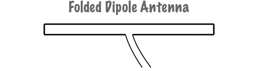
The folded dipole antenna consists of a basic dipole, but with an added conductor connecting the two ends together. This makes a ‘loop’ of wire that is a short circuit to DC. As the ends appear to be folded back, the antenna is called a folded dipole antenna.
The basic format for the folded dipole aerial is shown below. Like the basic dipole, the folded dipole antenna is a balanced antenna, and needs to be fed with a balanced feeder.
Unbalanced feeders can be used provided that a balun (unbalanced to balanced transformer) is used.
Additionally the most common form of folded dipole is the half wave version. It is centre fed in one of the lengths of wire. This means that it is fed where the current is at a high level and the voltage is low.
This means that like the standard half wave centre fed dipole it is fed at a low impedance point, although the impedance is higher than that of the standard half wave dipole.
The additional part of the folded dipole antenna is often made by using a wire or rod of the same diameter as the basic dipole section. However this is not always the case.
Also the wires or rods are typically equi-spaced along the length of the parallel elements. This can be achieved in a number of ways. Often for VHF or UHF antennas the rigidity of the elements is sufficient, but at lower frequencies spacers may need to be employed. To keep the wires apart. Obviously if they are not insulated it is imperative to keep them from shorting. In some instances flat feeder can be used.

One of the main reasons for using a folded dipole antenna is the increase in feed impedance that it provides. If the conductors in the main dipole and the second or "fold" conductor are the same diameter, then it is found that there is a fourfold increase (i.e. two squared) in the feed impedance. In free space, this gives an increase in feed impedance from 73Ω to around 300Ω ohms. Additionally the RF antenna has a wider bandwidth.
Folded dipole impedance increase theory
It is possible to reason why there is a four fold increase in impedance for the folded dipole antenna.
In a standard dipole antenna the currents flowing along the conductors are in phase and as a result there is no cancellation of the fields and as a result radiation or the signal occurs.
When the second conductor is added to make the folded dipole antenna this can be considered as an extension to the standard dipole with the ends folded back to meet each other.
As a result the currents in the new section flow in the same direction as those in the original dipole. The currents along both the half-waves are therefore in phase and the antenna will radiate with the same radiation patterns etc. as a simple half-wave dipole.
The impedance increase can be deduced from the fact that the power supplied to a folded dipole antenna is evenly shared between the two sections which make up the antenna. This means that when compared to a standard dipole the current in each conductor is reduced to a half. As the same power is applied, the impedance has to be raised by a factor of four to retain balance in the equation Watts = I2 x R.
Folded dipole transmission line effect
The folded element of the folded dipole antenna has a transmission line effect attached with it. It can be viewed that the impedance of the dipole appears in parallel with the impedance of the shorted transmission line sections, although the arguments for the impedance given above still hold true - it is just another way of looking at the same issue.
This can help to explain some of the other properties of the antenna.
The length is affected by this effect. Normally the wavelength of a standing wave in a feeder is affected by the velocity factor. If air is used, this will by around 95% of the free space value. However if a flat feeder with a lower velocity factor is used, then this will have the effect of shortening the required length.
The feeder effect also results in the folded dipole antenna having a flatter response, i.e. a wider bandwidth than a non-folded dipole.
It occurs because at a frequency away from resonance, the reactance of the dipole is of the opposite form from that of the sorted transmission line and as a result there is some reactance cancellation at the feed point of the antenna.
Folded dipole advantages
There are two main advantages for using a folded dipole antenna over a standard dipole:
- Increase in impedance: When higher impedance feeders need to be used, or when the impedance of the dipole is reduced by factors such as parasitic elements, a folded dipole provides a significant increase in impedance level that enables the antenna to be matched more easily to the feeder available.
- Wide bandwidth: The folded dipole antenna has a flatter frequency response - this enables it to be used over a wider bandwidth with many transmissions utilising a variety of different selectable channels, e.g. television and broadcast radio, a wide bandwidth antenna is needed. The standard dipole antenna does not always provide the required bandwidth and the additional bandwidth of the folded dipole meets the requirements .
Unequal conductor folded dipoles
On many occasions it can be necessary to implement impedance ratios to the standard 4:1 ratio that is normal for a folded dipole antenna. Simply by varying the effective diameter of the two conductors: top and bottom, different ratios can be obtained.

It is possible to determine the impedance step up ratio using the formula below:
Where:
d1 is the conductor diameter for the feed arm of the dipole
d2 is the conductor diameter for the non-fed arm of the dipole
S is the distance between the conductors
r is the step up ratio
It should be remembered that there is a shortening effect associated with the use of thick conductors as opposed to normal wire and this will have an effect on the length of the folded dipole.
Multiconductor folded dipoles
Although the concept of a folded dipole antenna often implies the use of one extra conductor, the concept can be extended further by adding additional conductors. This has the effect of increasing the overall impedance even more and further widening the bandwidth.

For the instance for a three wire folded dipole, with all wires or conductors having he same diameter, the impedance is increased by a factor of three squared, i.e. 9. This means that the nominal value for a folded dipole with three conductors is 9 times 73Ω or approximately 600Ω
Folded dipole applications
There are very many situations in which folded dipoles can be used. Their properties of a higher feed impedance than the straight centre fed half wave dipole and increased bandwidth provide an essential performance improvement required for many antenna systems.
There are several situations in which folded dipoles are used:
On their own: Folded dipole antennas are sometimes used on their own, but they must be fed with a high impedance feeder, typically 300 ohms. This on its own can be very useful in certain applications where balanced feeders may be used.
As part of another antenna: Folded dipoles find more uses when a dipole is incorporated in another RF antenna design with other elements nearby. The issue is that incorporating a dipole into an antenna such as a Yagi where elements are closely coupled reduces the feed impedance. If a simple dipole was used, then the feed impedance levels of less than 20 Ω or less can easily be experienced.
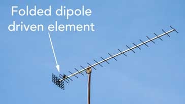
Folded dipole used within a TV Yagi antenna Using a folded dipole enables the impedance to be increased by a factor of four or whatever is required by having multiple wires in the folded dipole.
Increased bandwidth: Sometimes folded dipoles may be employed purely to give a greater bandwidth. When used to increase bandwidth, folded dipoles may be used on their own or within another antenna system.
Folded dipoles are seen in very many different places. Sometimes they are used on their own, but more often as the driven element in a more complicated antenna array. Here they provide additional bandwidth and also an increase in feed impedance to counteract the reduction in impedance caused by other elements within the overall antenna system.
More Antenna & Propagation Topics:
EM waves
Radio propagation
Ionospheric propagation
Ground wave
Meteor scatter
Tropospheric propagation
Antenna basics
Cubical quad
Dipole
Discone
Ferrite rod
Log periodic antenna
Parabolic reflector antenna
Phased array antennas
Vertical antennas
Yagi
Antenna grounding
Installation guidelines
TV antennas
Coax cable
Waveguide
VSWR
Antenna baluns
MIMO
Return to Antennas & Propagation menu . . .